F4000N_revD.pdf - 第114页
F4000N Series Operating Manual Section 8: M aintenance and Periodic Insp ection Part # 562187N - 1 Rev . D Sep. 2012 1 13 © 20 12 Fisnar Inc. 1.3 Check Metho ds Check point Check action (See if) Corrective action Tilt or…

F4000N Series Operating Manual
Section 8: Maintenance and Periodic Inspection
Part # 562187N-1
Rev. D Sep. 2012
112
© 2012 Fisnar Inc.
1. Check Cycles and Methods
1.1 General Consideration
It is essential to correctly and periodically inspect and maintain the robot to prevent
unexpected failures or malfunctions, thus ensuring safe operation and lengthening the
machine‟s life.
The outside parts of the machine should be kept clean. Use vacuum cleaner or soft cloth to
clean the machine. Do not use compressed air or chemical products to clean the machine,
as they can damage the internal cables, timing belts and other components of the unit.
Use only the greasing materials recommended by the manufacturer of the machine.
1.2 Check Cycles and Points
The check cycles of the machine are classified in the following categories:
Daily check
Weekly check
Check after every 3 months of operation
Check after every 3 years of operation
The checkpoints are as follows:
CHECK POINT
CHECK CYCLE
Daily
Weekly
Every
Every
3 months
3 years
Tilt or deviation of machine
X
Status of cables and hoses
X
Appearance
X
Stability on the work bench
X
Motor running condition
X
Motions, connections and joints
X
Unfastened / loose bolts and screws
X
Internal wires and connectors
X
Accuracy and precision
X
Ball screw assembly, LM guide, slide guide
X
Overhaul
X

F4000N Series Operating Manual
Section 8: Maintenance and Periodic Inspection
Part # 562187N-1
Rev. D Sep. 2012
113
© 2012 Fisnar Inc.
1.3 Check Methods
Check point
Check action (See if)
Corrective action
Tilt or deviation of machine
Robot working position is
tilted or inclined.
Set the machine in a
proper vertical position.
Status of cables and hoses
Electrical cables and
pneumatic hoses are
excessively twisted, bent, or
squeezed.
Air leakage between
pneumatic hoses and fittings.
Remove the any twists or
bends.
Cut away the damaged
parts of hoses and make
connections.
Appearance
Damage on the robot‟s head
from clashes during
operation.
Pay attention to working
area of robot and remove
any obstacle.
Stability on work bench
The robot is too close to the
edge of the work table.
Rearrange the position of
the robot on the table.
Remove sources causing
table vibration.
Motor running condition
Infiltration of grease.
Performance degradation due
to overload.
Replace motor (see
agent).
Motions, connections, and
joints
The axes are not moving
smoothly.
Noises, vibrations, and / or
shakes.
Grease up.
Reset and adjust gains
(contact agent for setting).
Unfastened / loose bolts and
screws
Loose or broken bolts and
nuts.
Tighten loose bolts and
nuts. Take corrective
action to remove the
cause.
Internal wires and connectors
Stripped or damaged external
cover or shield on cable
and/or connectors.
Replace the damaged
cables or connectors with
new ones (see agent).
Accuracy and precision
Z run out over X or Y larger
than 0.2mm.
Wear on timing belt.
Contact agent.
Replace timing belt (see
agent).
Ball screw (worm gear)
assembly, Linear Motion (LM)
guide, slide guide
Lack of grease on shaft, LM
guide and / or slide guide
surfaces.
Deflection of the shaft.
Apply grease on grease-
hole of worm gear, LM
guide, and slide guide
surfaces.
Replace the shaft (contact
agent).
Overhaul
Diagnose the whole system
and make decision for the
overhaul.
Contact agent.
F4000N Series Operating Manual
Section 8: Maintenance and Periodic Inspection
Part # 562187N-1
Rev. D Sep. 2012
114
© 2012 Fisnar Inc.
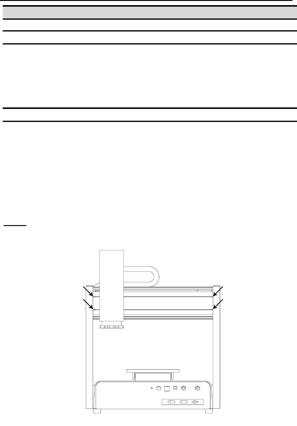
2. Greasing Procedure
2.1 Grease Type and Greasing Interval
Grease type: 30 – 100 centistokes. Recommended: THK brand white lithium grease
solid or spray, or equivalent.
Greasing period: every 6 months.
2.2 Accessing Parts to be Greased
a. Unscrew the bolts shown with arrows in the following pictures and remove
the covers.
b. Apply grease into the grease hole of ball screw (worm gear) and also thinly to
the surfaces of LM guide and slide guide.
c. Put back the covers and screw in the bolts.
X-Axis