F4000N_revD.pdf - 第55页
F4000N Series Operating Manual Section 5: Point T ype & Function Reference Part # 562187N - 1 Rev . D Sep 201 2 54 © 20 12 Fisnar Inc. 1.25 Dispense Output Setup Dispense Output Setup assigns the dispense output port…

F4000N Series Operating Manual
Section 5: Point Type & Function Reference
Part # 562187N-1
Rev. D Sep 2012
53
© 2012 Fisnar Inc.
1.20 Dummy Point
Registers the current XYZ location as a Dummy point. The tip will simply pass through this
point. A dummy point is useful for avoiding obstacles on the work piece.
1.21 Initialize
Registers an Initialize point causing the robot to perform a mechanical initialization. The tip
will home to position (0,0,0) and the robot will re-find the home position using the home
position sensors.
1.22 Label
Registers a label that can be used as a reference when used with the GOTO, Loop
address, Set I/O, Step & repeat X, Step & repeat Y and Call Subroutine commands.
Label can be used instead of Address number. A maximum of 64 labels is permitted per
program; each label can have up to 8 characters.
1.23 Display Counter
The Display Counter instruction shows a counter at the bottom of the teach pendant
screen while a program is running. Every time this instruction is executed, the counter
increases by one and is shown again on the screen. The counter begins at one (1).
1.24 Loop Counter
The Loop Counter either clears or keeps the current tally of the counter when an I/O signal
is received. The tally is cumulatively added to the current count on the display counter.
F4000N Series Operating Manual
Section 5: Point Type & Function Reference
Part # 562187N-1
Rev. D Sep 2012
54
© 2012 Fisnar Inc.
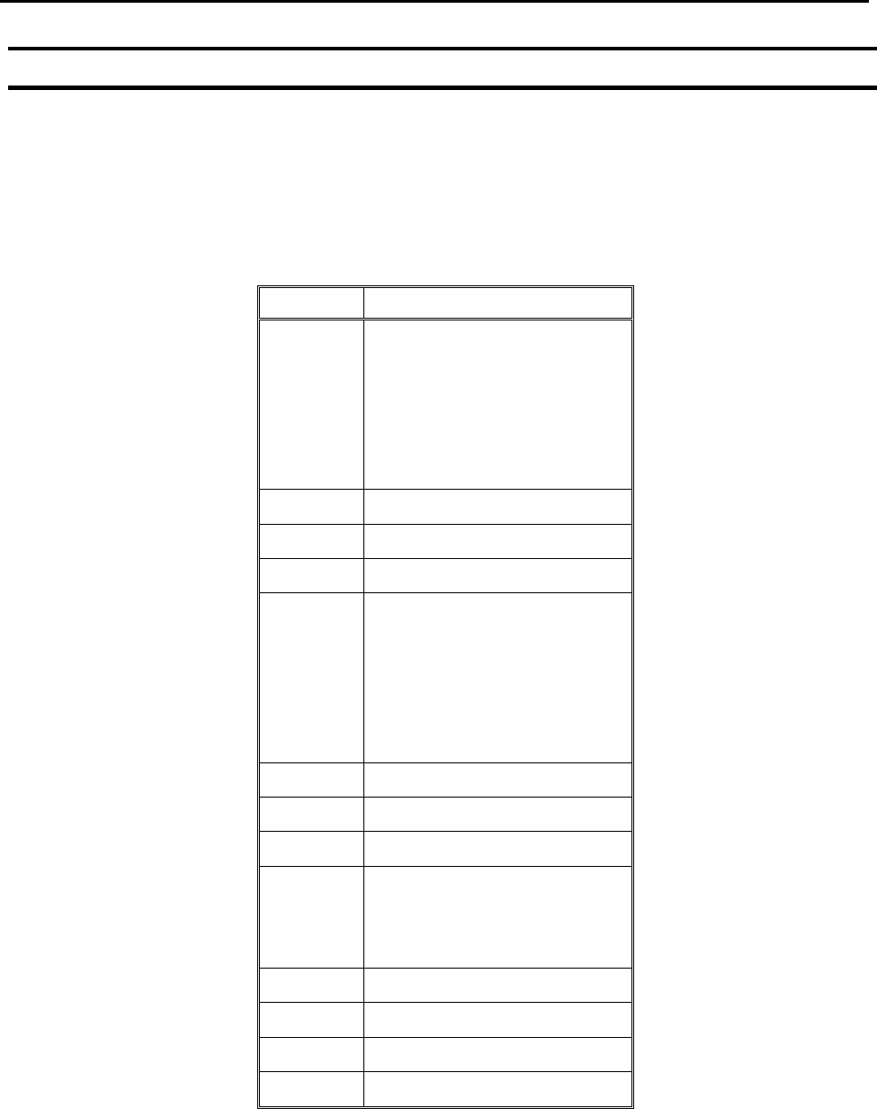
1.25 Dispense Output Setup
Dispense Output Setup assigns the dispense output port number (0-8) for the line and dot
under control of the line dispense setup and point dispense setup. The default dispense
output port number is zero.
Programming Sample:
Address
Instruction
1
Line Dispense Setup
Head Time: 0.1
Tail Time: 0.1
Node Time: 0
Tail Length: 0
2
Dispense Output: 3
3
Line Start
4
Line End
5
Line Dispense Setup
Head Time: 0.15
Tail Time: 0.1
Node Time: 0
Tail Length: 0
6
Dispense Output: 2
7
Line Start
8
Line End
9
Point Dispense Setup
Head time: 0.1
Tail time: 0.1
10
Dispense output: 1
11
Dispense Dot
12
Dispense Dot
End Program

F4000N Series Operating Manual
Section 5: Point Type & Function Reference
Part # 562187N-1
Rev. D Sep 2012
55
© 2012 Fisnar Inc.
2. F2 (Menu 1)
2.1 Group Edit
Group Edit is a powerful utility, which allows several different functions to be applied to a
user-defined group of addresses. These functions include copy, delete, move, multiply line
speed, multiply dispense times, apply X Offset, apply Y Offset, and apply Z Offset.
2.1.1 Copy
For example, to use group edit to copy addresses 1 – 20 in the current program to
memory address 21 - 40:
Instruction
Display Shows
1
Press the F2 (MENU 1) key, then 1 to select
Group Edit.
The display will prompt the user to enter the
starting memory address of the group to edit
(From) and the ending number of the group to
edit (To).
GROUP EDIT
FROM: 1
TO: 1
(1 <-> 4000)
F1: All F2: End
2
Type 1 then press ENTER to register 1 in From.
Type 20 then press ENTER to register 20 in To.
GROUP EDIT
ADDR: 1-20
------------------------
1.Copy 5.Dispense Time
2.Delete 6.Offset
3.Move 7.Offset (R.E)
4.Line Speed
Select:
3
The Group Edit menu will then appear, allowing
the user to select an operation to be applied to
the range of points.
Press 1 to select Copy. Then press ENTER.
GROUP COPY
------------------------
SOURCE 1-20
Destination:
4
The display will prompt the user to type the
destination memory address where the data will
be copied.
Press the Clear key to erase the old value, then
type 21 and press ENTER to select destination
memory address number 21.
GROUP COPY
SOURCE 1-20
Destination: 21
1.Yes 2.No
Select:
5
The display will now prompt the user to confirm
the copy. Press 1 and then press ENTER to
select Yes and perform the copy.