F4000N_revD.pdf - 第63页
F4000N Series Operating Manual Section 5: Point T ype & Function Reference Part # 562187N - 1 Rev . D Sep 201 2 62 © 20 12 Fisnar Inc. 2.2 Expand Step & Repeat Expand Step & Repeat will expand a step and repe…

F4000N Series Operating Manual
Section 5: Point Type & Function Reference
Part # 562187N-1
Rev. D Sep 2012
61
© 2012 Fisnar Inc.
2.1.7 Offset to
This function allows to be corrected automatically the offset problems which can appear
when changing the tip, the barrel and/or the item to be dispensed on.
Move the tip using the original coordinates stored in program memory with the MOVE
button. The next step is to jog the tip to the where it should be. The robot will realign all of
the data points with the original program.
Instruction
Display Shows
1
Press Move key. The tip will move to the
saved position that was recorded in the
current Address.
If the new tip location is slightly different from
the last tip location, you should see that the tip
is not exactly at the reference point.
Line Start X:50
Y:10
Z:35
X: 50, Y: 10, Z: 35
2
Jog the tip to the correct location for the
reference point.
Line Start X:50
Y:10
Z:35
X: 50.3, Y: 10.5, Z: 35
2
Press the F2 (MENU 1) key, then 1 to select
Group Edit. The display will prompt the user to
enter the starting memory address of the
group to edit (From) and the ending number of
the group to edit (To).
GROUP EDIT
FROM:1
TO:1
(1 <-> 4000)
F1:All F2:End
3
Type 1 then press ENTER to register 1 in
From.
Type 200 then press ENTER to register 200 in
To.
The Group Edit menu will then appear,
allowing the user to select an operation to be
applied to the range of points.
Press 7 to select Offset to. Then press ENTER
GROUP EDIT 1-200
1.Copy
5.Dispen.Time
2.Delete 6.Offset
3.Move 7.Offset to
4.Line Speed
Select:
4
The program origin will be adjusted for the
new tip location.
X:0.3, Y:0.5, Z:0.0
F4000N Series Operating Manual
Section 5: Point Type & Function Reference
Part # 562187N-1
Rev. D Sep 2012
62
© 2012 Fisnar Inc.
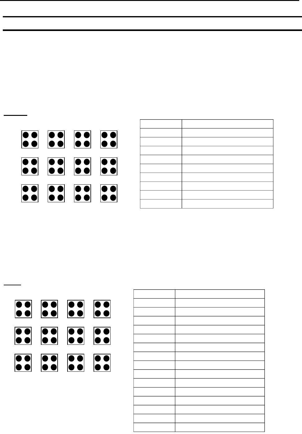
2.2 Expand Step & Repeat
Expand Step & Repeat will expand a step and repeat instruction to the actual data it
represents. This can be useful in situations where the user must edit selected elements in
a Step & Repeat group, although an expanded Step & Repeat instruction will occupy more
memory space than an unexpanded instruction.
For example, if the following program was created:
Before:
The original program occupies 9 memory addresses.
If the user brings memory address number 8 into the display and then selects F2 (MENU
1), Expand Step & Repeat, address 8 will be expanded into the 44 points which it
represents, bringing the total number of memory addresses used to 51 (plus the End
Program instruction at address 52).
After:
1
2
3
4
8
7
6
5
9
10
11
12
Address
Instruction
1
Dispense End Setup
2
Z Clearance
3
Point Dispense Setup
4
Dispense Point
5
Dispense Point
6
Dispense Point
7
Dispense Point
8
Step & Repeat X, Addr=4
9
End Program
1
2
3
4
8
7
6
5
9
10
11
12
Address
Instruction
1
Dispense End Setup
2
Z Clearance
3
Point Dispense Setup
4
Dispense Point
5
Dispense Point
6
Dispense Point
7
Dispense Point
8
Dispense Point
9
Dispense Point
10
Dispense Point
.
.
.
.
.
.
51
Dispense Point
52
End Program

F4000N Series Operating Manual
Section 5: Point Type & Function Reference
Part # 562187N-1
Rev. D Sep 2012
63
© 2012 Fisnar Inc.
2.3 Program Name
Program Name allows the user to register a name for the current program. If a program
name is registered, it will appear on the display when that program is selected in Run
mode.
2.4 Z-axis Limit (mm)
Z-axis Limit allows the user to limit the range of the Z-axis.
Use the Z and Z keys to bring the Z-axis to the highest and lowest point the Z-axis
should be allowed to travel (the highest Z-axis numeric value), then select F2 (Menu 1), 4.
Z-axis Limit. (mm)
The Z-axis range of motion will be limited to the current value.
2.5 Initial Output Port
Initial Output Port sets the ON/OFF status of the output signals at the start of each
program cycle.
Initial Output Port value is the decimal representation of an 8 binary bit values controlling
the 8 output signals.
For example,
Decimal
Value
Output Status
(X = on, blank = OFF)
#1
#2
#3
#4
#5
#6
#7
#8
0
1
X
2
X
4
X
8
X
16
X
32
X
64
X
128
X