00192377-02.pdf - 第102页
2 Retrofitting Instruct. S-23 HM t o SW V 502. xx incl. RV 6-DLM1 Head (O ption) SIPLACE S -23 HM 2.8 Sequence: M odifying Hardware 07/01 Issue 102 2.8.8.2 Instal ling the New Nozzle Changer (R V6) for 6-Segment Revolver…
SIPLACE S-23 HM 2 Retrofitting Instruct. S-23 HM to SW V 502.xx incl. RV6-DLM1 Head (Option)
07/01 Issue 2.8 Sequence: Modifying Hardware
101
CAUTION
Make certain that now screws or other hardware fall into the cutter during the following de-instal-
lation work. 2
WARNING
While retrofitting, also make certain that the DANGER symbol and the DANGER text are placed
on the cover of the cutter (see: Section 2.5). 2
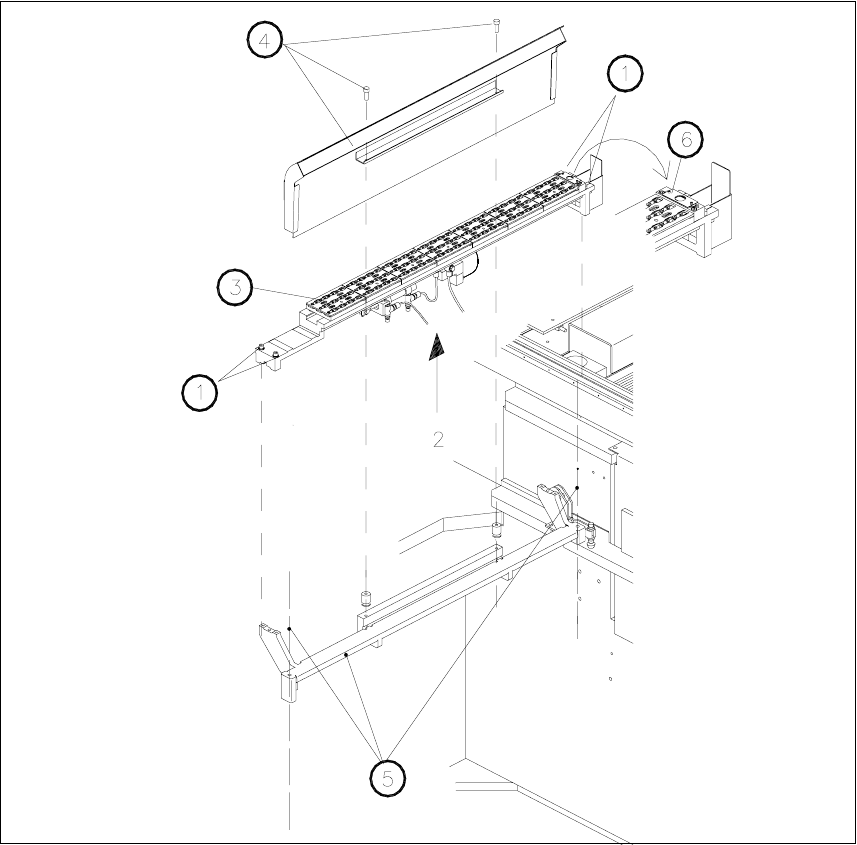
Å On the bottom of the nozzle changer, loosen the electrical and pneumatic connections (see:
Fig. 2.8.19), incl. cable tie on the nozzle changer (see: Fig. 2.8.20).
Å Remove the 12-segment nozzle changer (RV12 Standard):
Undo the 2 socket hex head cap screws M4 above the spacer bolts (as shown in Fig. 2.8.19).
Lift out the nozzle changer.
2 Retrofitting Instruct. S-23 HM to SW V 502.xx incl. RV6-DLM1 Head (Option) SIPLACE S-23 HM
2.8 Sequence: Modifying Hardware 07/01 Issue
102
2.8.8.2 Installing the New Nozzle Changer (RV6) for 6-Segment Revolver Head (DLM1)
Fig. 2.8.19 De-installing Nozzle Changer RV12 Standard / Installing Nozzle Changer RV6 Standard
Key:
1. Fastening screws for nozzle changer: 4 socket hex head cap screws M4
2. Electrical and compressed air connections on bottom of the nozzle changer
3. Nozzle changer for 12-segment revolver head, modular
4. Empty-tape duct (is not dismantled)
5. Carrier for empty-tape duct and nozzle changer, Item no. 00350480-01 (is not dismantled)
6. Bar with 2 fiducials (from retrofit kit) for nozzle changer; required for software version 502.01
SIPLACE S-23 HM 2 Retrofitting Instruct. S-23 HM to SW V 502.xx incl. RV6-DLM1 Head (Option)
07/01 Issue 2.8 Sequence: Modifying Hardware
103
Å Use the nozzle changer RV6 Standard from the retrofit kit:
Make the electrical and pneumatic connection on the bottom of the new nozzle changer as
shown below.
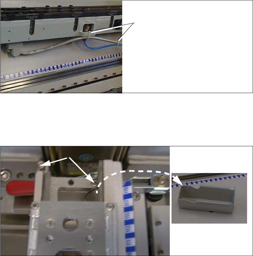
Fig. 2.8.20 Back of Nozzle Changer: Fastening Interface Cable and Compressed Air Hose
Å Fasten the interface cable of the nozzle changer and the compressed air hose to the back of
the new nozzle changer with a cable tie as shown above.
Å Place the new nozzle changer correctly into the fixed location pins of the carrier.
2
Fig. 2.8.21 Installing the New Nozzle Changer (PW RV6 Standard)
Key:
1. Reject box, removed
2. Screws fastening the nozzle changer RV6 Standard, RH side
Cable ties
2
1