00192377-02.pdf - 第103页
SIPLACE S-23 HM 2 Retrofitting Instruct. S-23 HM to SW V 502.xx incl. RV6-DLM 1 Head (Option) 07/01 Issue 2.8 Sequence: Modifying H ardware 103 Å Use the no zzle changer RV6 S tandar d from t he retro fit ki t: Make the …
2 Retrofitting Instruct. S-23 HM to SW V 502.xx incl. RV6-DLM1 Head (Option) SIPLACE S-23 HM
2.8 Sequence: Modifying Hardware 07/01 Issue
102
2.8.8.2 Installing the New Nozzle Changer (RV6) for 6-Segment Revolver Head (DLM1)
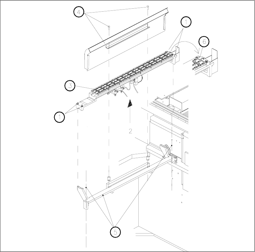
Fig. 2.8.19 De-installing Nozzle Changer RV12 Standard / Installing Nozzle Changer RV6 Standard
Key:
1. Fastening screws for nozzle changer: 4 socket hex head cap screws M4
2. Electrical and compressed air connections on bottom of the nozzle changer
3. Nozzle changer for 12-segment revolver head, modular
4. Empty-tape duct (is not dismantled)
5. Carrier for empty-tape duct and nozzle changer, Item no. 00350480-01 (is not dismantled)
6. Bar with 2 fiducials (from retrofit kit) for nozzle changer; required for software version 502.01
SIPLACE S-23 HM 2 Retrofitting Instruct. S-23 HM to SW V 502.xx incl. RV6-DLM1 Head (Option)
07/01 Issue 2.8 Sequence: Modifying Hardware
103
Å Use the nozzle changer RV6 Standard from the retrofit kit:
Make the electrical and pneumatic connection on the bottom of the new nozzle changer as
shown below.
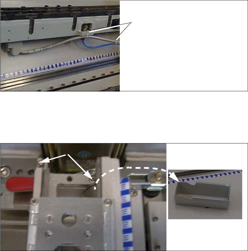
Fig. 2.8.20 Back of Nozzle Changer: Fastening Interface Cable and Compressed Air Hose
Å Fasten the interface cable of the nozzle changer and the compressed air hose to the back of
the new nozzle changer with a cable tie as shown above.
Å Place the new nozzle changer correctly into the fixed location pins of the carrier.
2
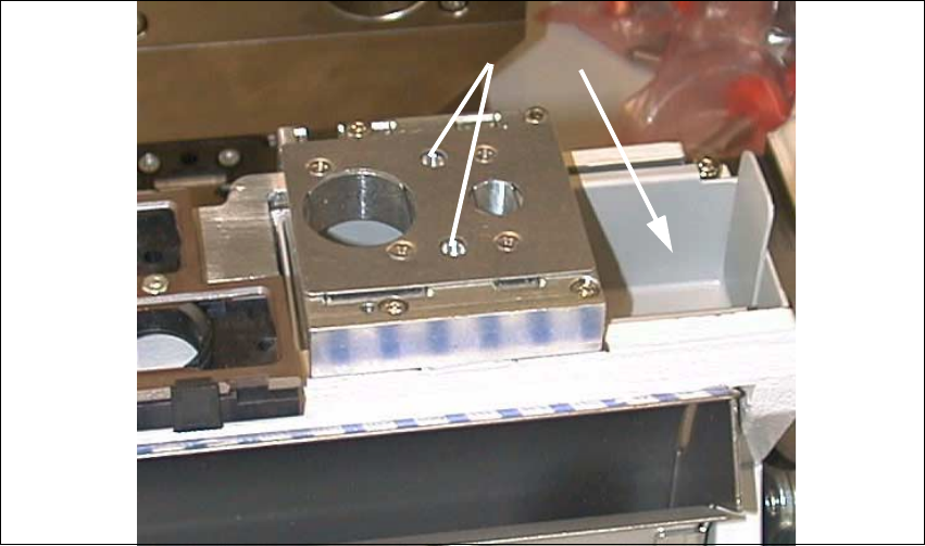
Fig. 2.8.21 Installing the New Nozzle Changer (PW RV6 Standard)
Key:
1. Reject box, removed
2. Screws fastening the nozzle changer RV6 Standard, RH side
Cable ties
2
1
2 Retrofitting Instruct. S-23 HM to SW V 502.xx incl. RV6-DLM1 Head (Option) SIPLACE S-23 HM
2.8 Sequence: Modifying Hardware 07/01 Issue
104
Å Remove the nozzle reject box and screw the nozzle changer on tight.
4 socket hex head cap screws M4 of different lengths, as follows:
– Back left -> M4 x 40
– Front left -> M4 x 50
– Back right -> M4 x 45
– Front right -> M4 x 10
2
Fig. 2.8.22 Nozzle Changer RV6 Standard Installed, Reject Box Inserted
Key:
1. Fiducials (already on the nozzle changer RV6 from the retrofit kit)
2. Reject box
Å Place the reject box from the nozzle changer back in.
2.8.9 Installation: Nozzle Changer Bar with Fiducials for Position Recognition
The bar from the retrofit kit must always be installed on the nozzle changer RV12 because the two
fiducials are required for SW V 502.01. 2
The fiducial marks are already on the new nozzle changer RV6. 2
2
1