00192377-02.pdf - 第105页
SIPLACE S-23 HM 2 Retrofitting Instruct. S-23 HM to SW V 502.xx incl. RV6-DLM 1 Head (Option) 07/01 Issue 2.8 Sequence: Modifying H ardware 105 Å Insert t he bar ( retrofit kit) at the rejec t pos ition of th e nozz le c…
2 Retrofitting Instruct. S-23 HM to SW V 502.xx incl. RV6-DLM1 Head (Option) SIPLACE S-23 HM
2.8 Sequence: Modifying Hardware 07/01 Issue
104
Å Remove the nozzle reject box and screw the nozzle changer on tight.
4 socket hex head cap screws M4 of different lengths, as follows:
– Back left -> M4 x 40
– Front left -> M4 x 50
– Back right -> M4 x 45
– Front right -> M4 x 10
2
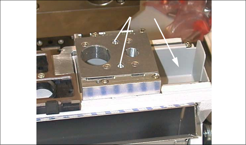
Fig. 2.8.22 Nozzle Changer RV6 Standard Installed, Reject Box Inserted
Key:
1. Fiducials (already on the nozzle changer RV6 from the retrofit kit)
2. Reject box
Å Place the reject box from the nozzle changer back in.
2.8.9 Installation: Nozzle Changer Bar with Fiducials for Position Recognition
The bar from the retrofit kit must always be installed on the nozzle changer RV12 because the two
fiducials are required for SW V 502.01. 2
The fiducial marks are already on the new nozzle changer RV6. 2
2
1
SIPLACE S-23 HM 2 Retrofitting Instruct. S-23 HM to SW V 502.xx incl. RV6-DLM1 Head (Option)
07/01 Issue 2.8 Sequence: Modifying Hardware
105
Å Insert the bar (retrofit kit) at the reject position of the nozzle changer and fasten it with the 2
socket hex head cap screws M3 (see: Fig. 2.8.19).
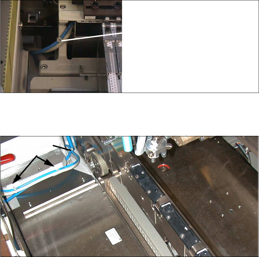
Fig. 2.8.23 Fastening the Cable and Compressed Air Hose on the Carrier for Nozzle Changer
Å Fasten the interface cable and the compressed air hose as shown above.
Fig. 2.8.24 Fastening the Cable and Pneumatic Hose of the Nozzle Changer to the Machine Frame
Key:
3. 2 Mounting pedestals, adhesive, with cable tie
4. Cable tie
Cable tie
2
3

2 Retrofitting Instruct. S-23 HM to SW V 502.xx incl. RV6-DLM1 Head (Option) SIPLACE S-23 HM
2.8 Sequence: Modifying Hardware 07/01 Issue
106
DANGER
Do not use alcohol for any cleaning work near open flame! 2
Å On the machine frame, degrease the area on which the 2 mounting pedestasl will be installed
(position, see: Fig. 2.8.22). Install the mounting pedestals.
Å Run the cable and the pneumatic hose and put on the cable ties (see: Fig. 2.8.22).
Å Remove all tools, etc., from the machine’s working area and close the doors of the machine
frame.