00192377-02.pdf - 第122页
2 Retrofitting Instruct. S-23 HM t o SW V 502. xx incl. RV 6-DLM1 Head (O ption) SIPLACE S -23 HM 2.13 Loading and Calibrating SITEST Nozzle Changer RV6 Standard with Nozzles 07/01 Issue 122 Å In con clus ion, chec k the…
SIPLACE S-23 HM 2 Retrofitting Instruct. S-23 HM to SW V 502.xx incl. RV6-DLM1 Head (Option)
07/01 Issue 2.13 Loading and Calibrating SITEST Nozzle Changer RV6 Standard with Nozzles
121
2.13.2 Calibrating Nozzle Changer RV6
Requirement: Loaded with nozzles as described in Section 2.13.1.
2
Å To measure / calibrate the new nozzle changer, select
the ICON "Nozzle changer magazine functions" .
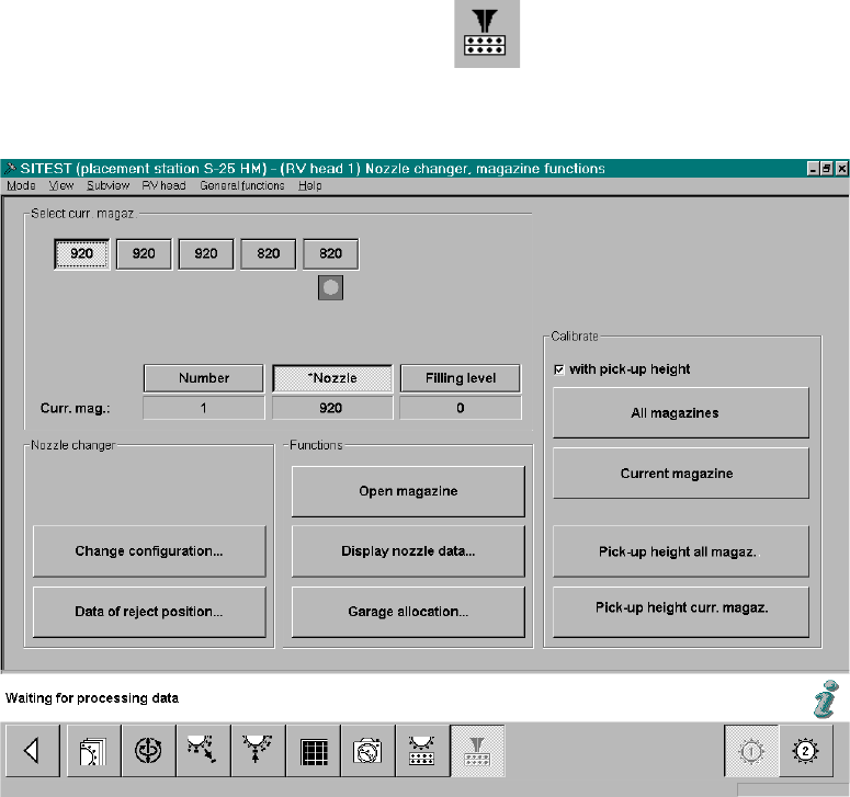
The following screeen for nozzle changer RV6 Standard will be displayed:
Fig. 2.13.4 SITEST: Nozzle Changer Magazine Functions (Example: RV6)
Å If necessary, check the magazine configuration with nozzles and the filling level "0" (buttons)
again -> see: Fig. 2.13.4.
Å In the field "Calibration", activate the function "with pickup height -> Select "All magazines"
(button):-> see: Fig. 2.13.4:
Å The calibration of the nozzle changer RV6 Standard follows.
First, the fiducials of the magazines and then the fiducials of the reject box are measured ->
Then the pick-up heights of the individual magazines are ascertained.
2 Retrofitting Instruct. S-23 HM to SW V 502.xx incl. RV6-DLM1 Head (Option) SIPLACE S-23 HM
2.13 Loading and Calibrating SITEST Nozzle Changer RV6 Standard with Nozzles 07/01 Issue
122
Å In conclusion, check the pick-up heights ascertained for EACH magazine individually:
Select the magazines in succession by clicking on the relevant button -> Select "Display nozzle
data" each time.
Å For EACH magazine individually, check the ascertained values in the last column:
– The max. permissible tolerance of all of the values of each magazine relative to each
neighboring magazine is +/-10 digits.
– The values of the last column of a magazine must be in the range between 870 to 929 digits.
Å If the values are okay, select "Settings" -> Store machine data".
Å If there are deviations, check the following:
Å Is the mounting surface of the nozzle changer holder satisfactory/clean?
Å Was the nozzle changed correctly? Does the nozzle move sluggishly on the sleeve?
Å After eliminating the cause of the problem, repeat the determination of the pick-up heights,
including checking and storing the values, as described above.
Å Close the SITEST program and restart the machine.
Å After installing an RV6 head or re-installing a head, continue the work with "RV mapping".
2.13.3 RV-Mapping
After installing an RV6 head or re-installing a head, carry out the"RV mapping". 2
Å Proceed as described in the Software guide SITEST V 502.xx.
2.13.4 Precision Calibration
Å
Carry out the precision calibration as described in the Software Guide SITEST V 502.xx.
2.13.5 Configuration: Automatic Shutoff of the Compressed Air
The automatic shutoff of the compressed air is activated as a cost-savings measure; therefore it
is not imperative - depends on the desires of the customer.
-> The setting is carried out in the station GUI by the operator/line engineer. 2
SIPLACE S-23 HM 2 Retrofitting Instruct. S-23 HM to SW V 502.xx incl. RV6-DLM1 Head (Option)
07/01 Issue 2.14 Sequence: Software Upgrade on Line Computer
123
2.14 Sequence: Software Upgrade on Line Computer
Å At the very latest, use the Software Version Description LRU.502.xx now (Item no. see: Section
2.7), to check whether the REQUIREMENTS for the upgrade exist.
Å Refere to the above-mentioned Software Version Description regarding all new func-
tions / sequences.
Å You need the software LRU V502.01:
Boot-up and installation disk and CD, Item no. 00358516-01.
Å Use the above-mentioned description to install the software LRU V 502.01:
Å While upgrading, follow the procedures for central data maintenance (see: Software Ver-
sion Description, Section "Installation Instructions/Upgrade Instructions").
Å Follow the sequence of the steps at the line computer UNIX:
- for the upgrading process/conversion of S-23 HM to S-25 HM and
- for the procedure while copying the setup from an S-23 HM to an S-25 HM,
as set forth in the section "New Functions" in the above-mentioned version description.
Å At the line computer, in the configuration editor (details, see: Software Version Description
LRU V 502.xx), adapt the software version of the individual stations on the line to the ver-
sion actually at the station in question.
2.15 Line Computer: Configuration of RV6 Head, Nozzle
Changer RV6, etc.
Å Due to the multitude of new characteristics of the software, proceed as described in the Soft-
ware Version Description LRU V 502.xx.
Å After the upgrade, define a new station in the station editor as S25 HM (= new station type),
with the relevant placement heads and options.
Å Existing setups can be transformed via the RT converter as described in detail in the Software
Version Description LRU V 502.xx.
2
q