00192377-02.pdf - 第78页
2 Retrofitting Instruct. S-23 HM t o SW V 502. xx incl. RV 6-DLM1 Head (O ption) SIPLACE S -23 HM 2.8 Sequence: M odifying Hardware 07/01 Issue 78 2.8 S equence : Modi fying Hard ware 2.8.1 De-inst alling the T ouch-S cr…

SIPLACE S-23 HM 2 Retrofitting Instruct. S-23 HM to SW V 502.xx incl. RV6-DLM1 Head (Option)
07/01 Issue 2.7 Required Documents
77
2.7 Required Documents
– Software Version Description for Station V 502.01, Item no. 00192395-01 (G + E)
– Software Guide SITEST V 502.xx, Item no. 00192656-01 (E)
– Software version description, LRU V 502.01, Item no. 00192397-01 (G + E)
– Technical Information No. 34V05060 *)
– For the installation of options in connection with upgrading:
– 6-segment revolver head, modular:
Conversion instructions DLM1 Collect & Place head, Item no. 00191684-03 (G + E).
– Setting instructions for SIPLACE S-25 HM, Item no. 00192192-02 (G + E)
– Retrofitting instructions for MTC on S-25 HM, Item no. 00192792-02 (G + E)
– Retrofitting instructions "Head board, modular, Item no. 00192919-01 (G + E) -> in
progress,
Partial information, e. g., photos, Item nos. PCBs
, new cables required, etc. -> see: retro-
fitting instructions "PCB camera Multicolor..." (below)
– Retrofitting instructions
"PCB camera Multicolor on S-25 HM and HS-50", Item no. 00192232-01 (G + E);
-> Requirement: Retrofitting of the modular head boards at both gantries.
*) ATTENTION: This documentation is intended for INTERNAL use only.
When finished, put the documentation back with your papers.
NOTE:
These instructions contain the retrofitting of the nozzle changer RV6 Standard (for 6-segment re-
volver head DLM1) (see: Section 2.8.8). 2

2 Retrofitting Instruct. S-23 HM to SW V 502.xx incl. RV6-DLM1 Head (Option) SIPLACE S-23 HM
2.8 Sequence: Modifying Hardware 07/01 Issue
78
2.8 Sequence: Modifying Hardware
2.8.1 De-installing the Touch-Screen Driver
Å Your first step should be to de-install the old touch-screen driver as follows:
Settings -> System control -> Software -> "Monitor-Mice" -> Remove.
2.8.2 Preparatory Steps
Å Push the gantry/placement head into the area over the PCB conveyor.
The function for changing the component table - "All gantires in set-up position" - exists only
with Version 502.01 and later).
Å Undock the movable component changeover table from the machine and move it out of the
machine.
Å Turn the machine OFF; isolate it from the mains; turn the compressed air OFF at the com-
pressed air unit and bleed the needle valve on the compressed air unit (see DANGER text in
Section 2.4).
2.8.3 Installing the Conveyor Control TSP 210 and the I/O Boards KSP 219
DANGER
Comply with the safety notes in Section 2.4.
Comply with DIN EN 60204 during all work inside the machine frame. 2
Described below is the exchange of the I/O boards KSP-P218-A32 by the I/O subsystem consist-
ing of the assemblies:
– KSP-P219-A32 (I/O board),
– TSP-210 (conveyor control) and
– Backplane P219
You will need:
Conversion kit "URS S23HM auf SW502 incl. head, modular", Item no. 00356654-01
Å Open the folding doors of the machine frame at the control unit/terminal panel, left board slot.
SIPLACE S-23 HM 2 Retrofitting Instruct. S-23 HM to SW V 502.xx incl. RV6-DLM1 Head (Option)
07/01 Issue 2.8 Sequence: Modifying Hardware
79
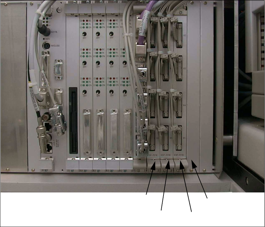
Fig. 2.8.1 View of Control Unit before Modification
Å In the control unit, pull the following from I/O boards KSP-P218-A32
(SMP board slot 8 – 10, see: Fig. 2.8.1): 12 connectors X2se – X5se, X2sf – X5sf, X2sg – X5sg.
Å Remove the 3 I/O boards KSP-P218-A32 (see: Fig. 2.8.1).
Å Take the front panel off SMP board slot 11 (see: Fig. 2.8.1).
Å At the top right of the control unit, remove the screw fastening the control unit (1 socket hex
head cap screw M5, size 4).
Å Make certain that none of the cables are pinched or are under tension:
Carefully pull out the control unit, disconnect it from the guide and set it down.
Front panel
SMP board slot
SMP board slot 8
KSP-P218 (se)
KSP-P218 (sg)
SMP board slot 10
KSP-P218 (sf)
SMP board slot 9