00192377-02.pdf - 第83页
SIPLACE S-23 HM 2 Retrofitting Instruct. S-23 HM to SW V 502.xx incl. RV6-DLM 1 Head (Option) 07/01 Issue 2.8 Sequence: Modifying H ardware 83 Å Fasten the back plane w ith the 8 s crews M 2.5 from t he retro fit kit: T …
2 Retrofitting Instruct. S-23 HM to SW V 502.xx incl. RV6-DLM1 Head (Option) SIPLACE S-23 HM
2.8 Sequence: Modifying Hardware 07/01 Issue
82
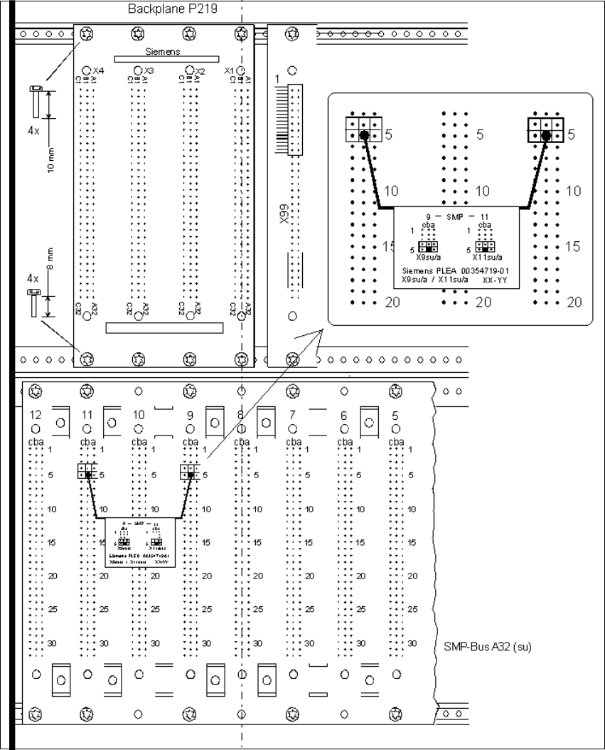
Fig. 2.8.4 Installing Backplane P219 and the Interrupt Connection
Å Install the new backplane P219 (from the retrofit kit) above the SMP board slots 8-11, see: fig-
ure above:
While doing so, align the backplane such that the board slots are in a line with those of the SMP
backplane. The connector designations X1-X4 on the back must be at the top.
SIPLACE S-23 HM 2 Retrofitting Instruct. S-23 HM to SW V 502.xx incl. RV6-DLM1 Head (Option)
07/01 Issue 2.8 Sequence: Modifying Hardware
83
Å Fasten the backplane with the 8 screws M2.5 from the retrofit kit:
To do so, use 4 screws M2.5 x 10 screws for the top row and 4 screws M2.5 x 8 for the bottom
row.
Å If you unplugged the connector from X99, plug it back in.
Å Plug the connector for the Interrupt TSP-210 machine controller (from the retrofit kit) on the
SMP backplane: To do so, plug the connector cable on the back of SMP board, slot 9, and
board slot 11 onto the plug connectors as shown in Fig. 2.8.4.
Å Re-install the cover 007 (see Fig. 2.8.2).
Å Make certain that none of the cables are pinched or are under tension:
Install the control unit and fasten it with the screw M5.
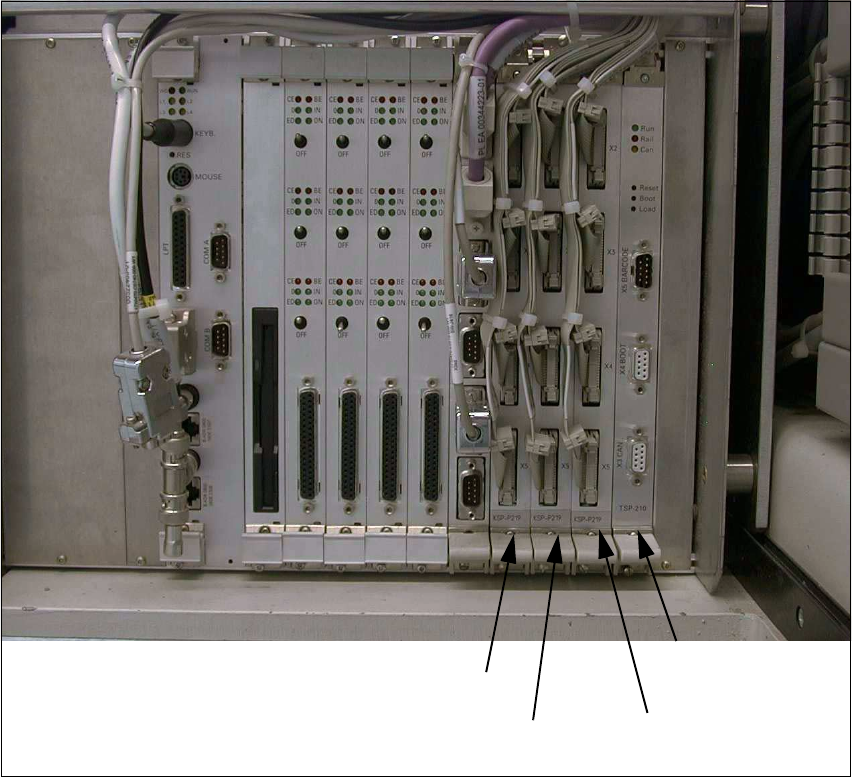
Fig. 2.8.5 View of the Control Unit after Modification
Å Plug in the 3 new I/O boards KSP-P219-A32 (from the retrofit kit) onto the SMP board slot 8-
10 (see: Fig. 2.8.5).
KSP-P219 (se)
SMP board slot 8
TSP-210
SMP board slot 11
KSP-P219 (sg)
SMP board slot 10
KSP-P219 (sf)
SMP board slot 9
2 Retrofitting Instruct. S-23 HM to SW V 502.xx incl. RV6-DLM1 Head (Option) SIPLACE S-23 HM
2.8 Sequence: Modifying Hardware 07/01 Issue
84
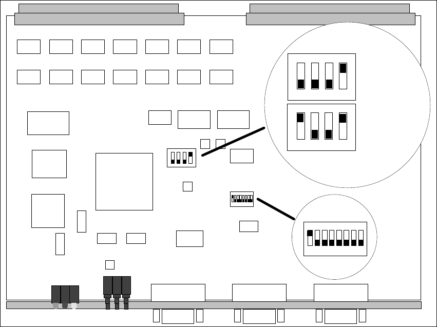
Fig. 2.8.6 Setting the DIL Switches
Å ATTENTION: Set the new assembly TSP-210 on the quad DIL switches S1 to Single or
Dual Conveyor (Fig. 2.8.6):
– Switch 1 to OFF in case of single conveyor 1,
– Set to ON in case of dual conveyor.
Å Install the assembly TSP-210 on SMP board slot 11: Fig. 2.8.5.
Å Plug the 12 connectors X2se – X5se (board at board slot 8), X2sf – X5sf (board at board slot
9), X2sg – X5sg (board at board slot 10) onto the I/O boards.
Å The firmware is not installed until all mechanical installation steps have been concluded, pref-
erably BEFORE installing the SW V 502.01 at the station (see: Section 2.9).
ON
1 2 3 4
12345678
ON
12345678
ON
S1
S2
S2
ON
1234
S1
ON
1234
Einfachtransport
Single Conveyor
Doppeltransport
Double Conveyor