00192377-02.pdf - 第89页
SIPLACE S-23 HM 2 Retrofitting Instruct. S-23 HM to SW V 502.xx incl. RV6-DLM 1 Head (Option) 07/01 Issue 2.8 Sequence: Modifying H ardware 89 Fig. 2.8.10 View of the Bottom of the PC Carrier 3: Securing the e156 A dapte…
2 Retrofitting Instruct. S-23 HM to SW V 502.xx incl. RV6-DLM1 Head (Option) SIPLACE S-23 HM
2.8 Sequence: Modifying Hardware 07/01 Issue
88
2.8.6 Up to Serial No. 350 incl.: Replace 14" monitor by 15" e156 monitor
NOTE:
The new 15" monitor incl. monitor carrier must be installed if there is still a 14" monitor.
To do so first install the adapter e156 at the PC carrier 3, fuctional status 01 and/or 02 (see also
explanation in Section 2.2). 2
Å Disconnect all connections from the back of the monitor.
Å Disconnect the keyboard, if necessary disconnect the component barcode scanner and re-
move the keyboard from the carrier.
Å Carefully lift the 14" monitor off the carrier (see Fig. 2.8.11).
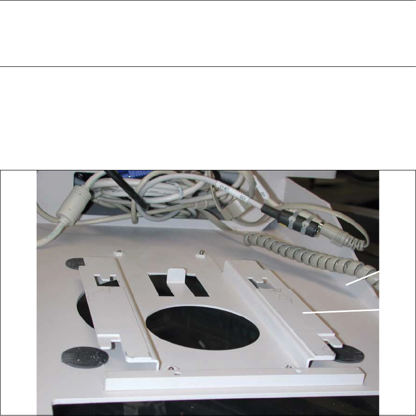
Fig. 2.8.9 View of the Top of the PC Carrier 3: Adapter e156
Key:
1. PC carrier 3 (status 01 or 02)
2. Adapter e156
Å Place the adapter e156 (Item no. see Section 2.5.5) from above over the large round aperture
in the PC carrier 3 (status 01 or 02), as shown above.
Å Secure the e156 adapter to the PC carrier from the bottom of the PC carrier (see Fig. 2.8.10):
4 washers and 4 socket hex head cap screws M4 (included in Item no. 00357744S01).
2
1
SIPLACE S-23 HM 2 Retrofitting Instruct. S-23 HM to SW V 502.xx incl. RV6-DLM1 Head (Option)
07/01 Issue 2.8 Sequence: Modifying Hardware
89
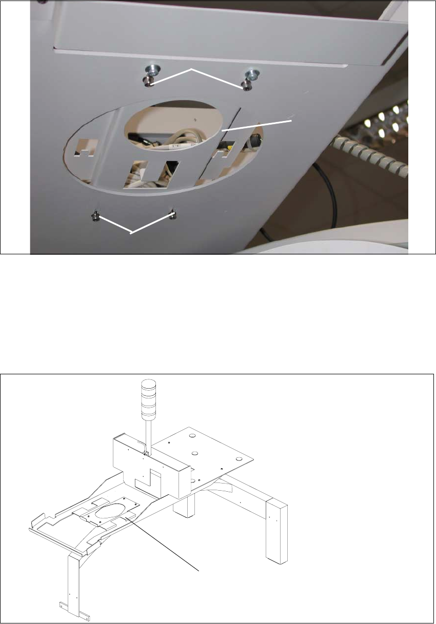
Fig. 2.8.10 View of the Bottom of the PC Carrier 3: Securing the e156 Adapter
Key:
1. Adapter e156
2. Fastening of the adapter e156:
4 socket hex head cap screws M4 x 10, 4 washers 4,3 DIN 9021-A
Fig. 2.8.11 PC Carrier 3: Adapter e156 for 15" Monitor e156 mounted
2
1
2
Adapter e156,
mounted on
PC carrier 3

2 Retrofitting Instruct. S-23 HM to SW V 502.xx incl. RV6-DLM1 Head (Option) SIPLACE S-23 HM
2.8 Sequence: Modifying Hardware 07/01 Issue
90
Å Carefully place the computer on the carrier and make the connections.
Å Place the 15" monitor e156 (Item no see Section 2.5.5) carefully on the carrier and make the
connections.
Å Place the keyboard back on the carrier and make the connections (if applicable, also those of
the component bar code scanner).
Å Iff no 6-segment revolver head is installed, proceed by installing the new bar with fiducials on
the nozzle changer RV 12 Standard -> see: Section 2.8.9.
2.8.7 Optional: Installing the 6-Segment Revolver Head (RV6-DLM1)
NOTE:
If you install the option PCB camera Multicolor during the upgrade, the modular head board must
also be installed. This is always true for both gantries.
-> See pertinent retrofitting instructions (Item no. see: Section 2.7). 2
You will require: 2
– Conversion instructions, Item no. 00191684-03 (G + E)
– Conversion kit "6 C&P-head R-configuration kit" (option), Item no. 00117261-01
NOTE:
The document "Conversion Instructions" describes the preparation of the new head (raising of the
vacuum generator and the fastening of the ribbon cables).
This is supplemented by the following description of the entire process including de-installation
and installation. 2