00192377-02.pdf - 第91页
SIPLACE S-23 HM 2 Retrofitting Instruct. S-23 HM to SW V 502.xx incl. RV6-DLM 1 Head (Option) 07/01 Issue 2.8 Sequence: Modifying H ardware 91 2.8.7.1 De-inst allation of the 12-Segment Rev olver head (DLM1) 2 Fig. 2.8.1…

2 Retrofitting Instruct. S-23 HM to SW V 502.xx incl. RV6-DLM1 Head (Option) SIPLACE S-23 HM
2.8 Sequence: Modifying Hardware 07/01 Issue
90
Å Carefully place the computer on the carrier and make the connections.
Å Place the 15" monitor e156 (Item no see Section 2.5.5) carefully on the carrier and make the
connections.
Å Place the keyboard back on the carrier and make the connections (if applicable, also those of
the component bar code scanner).
Å Iff no 6-segment revolver head is installed, proceed by installing the new bar with fiducials on
the nozzle changer RV 12 Standard -> see: Section 2.8.9.
2.8.7 Optional: Installing the 6-Segment Revolver Head (RV6-DLM1)
NOTE:
If you install the option PCB camera Multicolor during the upgrade, the modular head board must
also be installed. This is always true for both gantries.
-> See pertinent retrofitting instructions (Item no. see: Section 2.7). 2
You will require: 2
– Conversion instructions, Item no. 00191684-03 (G + E)
– Conversion kit "6 C&P-head R-configuration kit" (option), Item no. 00117261-01
NOTE:
The document "Conversion Instructions" describes the preparation of the new head (raising of the
vacuum generator and the fastening of the ribbon cables).
This is supplemented by the following description of the entire process including de-installation
and installation. 2
SIPLACE S-23 HM 2 Retrofitting Instruct. S-23 HM to SW V 502.xx incl. RV6-DLM1 Head (Option)
07/01 Issue 2.8 Sequence: Modifying Hardware
91
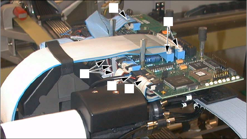
2.8.7.1 De-installation of the 12-Segment Revolver head (DLM1)
2
Fig. 2.8.12 De-installation of the RV12 Placement Head, DLM1: Removing the Connections
Key:
1. Ribbon cable "Vacuum board"
2. Round cable "Revolver head" (motor, tachometer)
3. 3 ribbon cables "Stepped motors/Photoelectric barrier"
4. 1 ribbon cable "Illumination PCB camera (illlumination board)
5. 2 ribbon cables, wide
Å Remove the 4 protective covers from the placement head and unscrew socket hex head cap
screws M3 and 2.5.
Å Undo the connectors of the front part of the placement head at the "Conversion board, small
axis" and on the illumination board (see: Fig. 2.8.12 -> 1 to 5).
2
1
3
5
4
2 Retrofitting Instruct. S-23 HM to SW V 502.xx incl. RV6-DLM1 Head (Option) SIPLACE S-23 HM
2.8 Sequence: Modifying Hardware 07/01 Issue
92
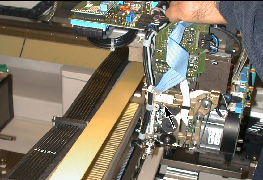
2
Fig. 2.8.13 Undoing Screws Fastening Cable Harness; Undoing Connections on Conversion Board
Å Undo the screw fastening the cable clamp that holds the cable harness running downward
(see: arrow, Fig. 2.8.13, 1 socket hex head cap screw M3).