00192377-02.pdf - 第94页
2 Retrofitting Instruct. S-23 HM t o SW V 502. xx incl. RV 6-DLM1 Head (O ption) SIPLACE S -23 HM 2.8 Sequence: M odifying Hardware 07/01 Issue 94 2.8.7.2 Prepa ring the New 6-Segment Revolver Head (RV6-DLM1) 2 Fig. 2.8.…
SIPLACE S-23 HM 2 Retrofitting Instruct. S-23 HM to SW V 502.xx incl. RV6-DLM1 Head (Option)
07/01 Issue 2.8 Sequence: Modifying Hardware
93
2
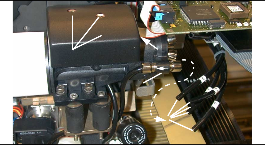
Fig. 2.8.14 De-installation 12-Segment Rev. Head: Detaching Pneumatic Hoses from Vacuum Generator
Key:
1. Compressed air feeder to the vacuum generator (5 hoses)
2. Collar on compressed air connection to the blast unit (support while pulling hoses off).
3. Cover over vacuum distributor board
(Fasteners: 2 socket hex head cap screws M2.5)
4. Ribbon cable: Connection on vacuum distributor board
Å Pull off the 5 compressed air hoses on the vacuum generator (see: Fig. 2.8.14).
Support in the case of the quick-release coupling (-> 2).
Å Remove the cover from the vacuum distributor board (loosen 2 socket hex head cap screws
M2.5, size 3).
Å Pull the 2 silicone hoses off the vacuum distributor board.
Å Pull the 2 silicone hoses off the silencer.
Å Support the placement head:
Undo the screws fastening the placement head: 3 socket hex head cap screws M4.
The head is still held in position by pins.
Å Pull the placement head (pins in the part to be pulled off) off the back part and set it down such
that it is not damaged, preferably in the proper package.
2
1
3
4
2
2 Retrofitting Instruct. S-23 HM to SW V 502.xx incl. RV6-DLM1 Head (Option) SIPLACE S-23 HM
2.8 Sequence: Modifying Hardware 07/01 Issue
94
2.8.7.2 Preparing the New 6-Segment Revolver Head (RV6-DLM1)
2
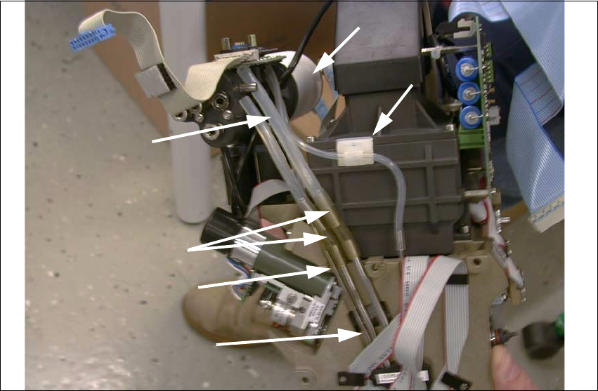
Fig. 2.8.15 New Placement Head: Mounting 3 Extensions (Steel Tubes), BOTTOM
Key:
1. Vacuum generator with silencer (fasteners: 4 socket hex head cap screws M4)
2. Silicone hoses am the vacuum distributor
3. NEW extension to be installed:
2 tubes 35 mm long (enclosed package in the retrofit kit, see: Section 2.5)
4. NEW extension to be installed:
1 tube 30 mm long (enclosed package in the retrofit kit, see: Section 2.5)
5. Vacuum feeders to the star (metal tube, fixed).
6. Vacuum hose, fastened with round-cable clamp (vacuum check for holding circuit).
Å Take the 6-Segment revolver head (DLM1) out of the retrofit kit.
Å Pull the silicone hoses of the vacuum generator and the vacuum board off the new placement
head.
Å Remove the vacuum generator incl. silencer from the new placement head so that you can
mount the metal-rubber vibration dampers from the enclosure pack later:
Undo 4 socket hex head cap screws M4 (see: and Fig. 2.8.16 and Fig. 2.8.18).
2
3
5
4
6
1

SIPLACE S-23 HM 2 Retrofitting Instruct. S-23 HM to SW V 502.xx incl. RV6-DLM1 Head (Option)
07/01 Issue 2.8 Sequence: Modifying Hardware
95
NOTE:
If metal brackets are still installed in the present 12-segment revolver head (RV12-DLM1) instead
of rubber-metal vibration dampers, these brackets must be exchanged for these dampers as
described below for the 6-segment revolver head DLM1). 2
Å Extend the length of the vacuum hoses as outlined in the conversion instructions, Item no.
00191684-03:
Push the extensions (tube from the retrofit kit) onto the FIXED metal tubes = BELOW (see: Fig.
2.8.15).
Place the existing hose pieces onto the tube in the correct order (length!).
Å Now install the Velcro-type fastener on the bottom of the head board because this location is
better accessible before the head is installed (see: Fig. 2.8.17).
Å The vacuum generator with silencer remains dismantled for the time being because it is more
practical not to mount this until after you have installed the placement head.
Å Mount the placement head as described below.