00192377-02.pdf - 第97页
SIPLACE S-23 HM 2 Retrofitting Instruct. S-23 HM to SW V 502.xx incl. RV6-DLM 1 Head (Option) 07/01 Issue 2.8 Sequence: Modifying H ardware 97 Å Place the new V elc ro-typ e fastener s (enclo sed packag e from retrofi t …
2 Retrofitting Instruct. S-23 HM to SW V 502.xx incl. RV6-DLM1 Head (Option) SIPLACE S-23 HM
2.8 Sequence: Modifying Hardware 07/01 Issue
96
2.8.7.3 Installing the New 6-Segment Revolver Head (RV6-DLM1)
NOTE:
If the optional PCB camera Multicolor will be installed during the upgrading process, the modular
head board must now be installed first (retrofitting instructions (Item no. see: Section 2.7). This
modification must always be performed on both gantries because the Multicolor camera is always
installed on both gantries. 2
2
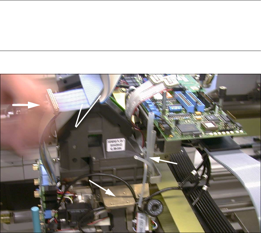
Fig. 2.8.16 Pushing the 6-Segment Revolver Head onto Pins of the Head Support and Screwing It Tight
Key:
1. 4 silicone hoses, connection to silencer and vacuum generator
2. Vacuum generators with silencers are still dismantled at this point.
3. Push placement head on.
4. Re-use 2 wide ribbon cables from the de-installed head.
(Do this with ribbon cable "Illumination board" also -> see: Fig. 2.8.12)
Å The silencer has not been installed yet (see: Fig. 2.8.16 -> 2).
Å Push the placement head which has been thus prepared (3 extended vacuum tubes) onto the
back portion on the gantry:
Screw the head tight (3 socket hex head cap screws M4).
1
3
4
2
SIPLACE S-23 HM 2 Retrofitting Instruct. S-23 HM to SW V 502.xx incl. RV6-DLM1 Head (Option)
07/01 Issue 2.8 Sequence: Modifying Hardware
97
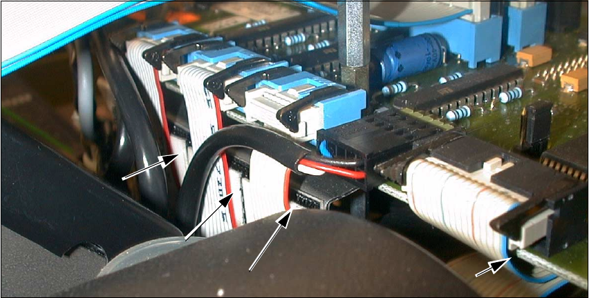
Å Place the new Velcro-type fasteners (enclosed package from retrofit kit) onto the 3 narrow rib-
bon cables (see: Fig. 2.8.17).
Fig. 2.8.17 Atttaching the Velcro-Type Fasteners
Key:
1. Velcro-type fastener under the ribbon cables (3 cables "Stepped motors")
2. Velcro-type fastener on the bottom "Conversion board, small axis" (cable "Vacuum board")
Å When the modular head board is installed, the strain relief devices remain mounted on the fe-
male connectors of the new cables (which are on the new head).
Å ONLY when the "Conversion board, small axis" is present: Remove the strain relief bows from
ALL ribbon cables of the NEW placement head.
The new cables are held on each of the connectors of the conversion board by 2 black terminal
strips on the left and right (see: Fig. 2.8.18 -> 5).
Å Pull the 2 wide ribbon cables off the dismantled placement head and connect them to the new
6-segment revolver head:
Take note of: This cable is different for the modular head board than for the "Conversion board,
small axis".
Å Lay the two wide ribbon cables as shown in Fig. 2.8.12.
Å Make the plug-in connections on the board and placement head.
Å Secure the cables with the ribbon cable clamp (see: Fig. 2.8.12).
Å Pull the ribbon cable "Illumination" off the dismantled head and make the connection to the il-
lumination board and the new head. Take note of:
This cable is different for the modular head board than for the "Conversion board, small axis".
2
1
1
1

2 Retrofitting Instruct. S-23 HM to SW V 502.xx incl. RV6-DLM1 Head (Option) SIPLACE S-23 HM
2.8 Sequence: Modifying Hardware 07/01 Issue
98
Å Make the connections of the 3 ribbon cables "Stepped motor" and the round cable "Revolver
head" (motor, tachometer) on the board.
Press the 3 ribbon cables with the 3 Velcro-type connections against the board holder.
Å Install the 4 new rubber-metal vibration dampers from the retrofit kit on the new head
(see: Fig. 2.8.18 -> 1), as described in detail in the conversion instructions
DLM1 Col-
lect&Place head, Item-No. 00191684-03.
CAUTION
If, instead of the rubber-metal vibration dampers, a metal bracket is still installed on the remaining
RV12-DLM1 head, the bracket must be replaced by the dampers (from a 2 enclosed package).
De-install the vacuum generator incl. silencer and proceed as described in the conversion instruc-
tions (see above). 2
Å Place the vacuum generator incl. silencer on the adapter plate and screw it tight (4 washers
A 4.3 und 4 socket hex head cap screws M4; size 3, in the enclosed package).
The enclosed package contains all fastening parts.
Å If applicable, remove the cover from the vacuum generator (2 socket hex head cap screws
M2.5; size 2).
Å Connect the ribbon cable "Vacuum board" to the conversion board / modular head board.
Secure it to the bottom of the board with the Velcro-type fastener (see: Fig. 2.8.18 -> 2).
For details -> see: conversion instructions for the DLM1 head.
Å Fold down all black terminal strips (see: Fig. 2.8.18 -> 5).