fx3r.pdf - 第185页
FX-3R Maintenance Guide 13-16 13-4. Control Unit 13-4-1. Structure of Control Unit Figure 13-4-1-1 shows the board layout drawing of the control unit. Check that the boards are mounted correctly while referring to these …
FX-3R Maintenance Guide
13-15
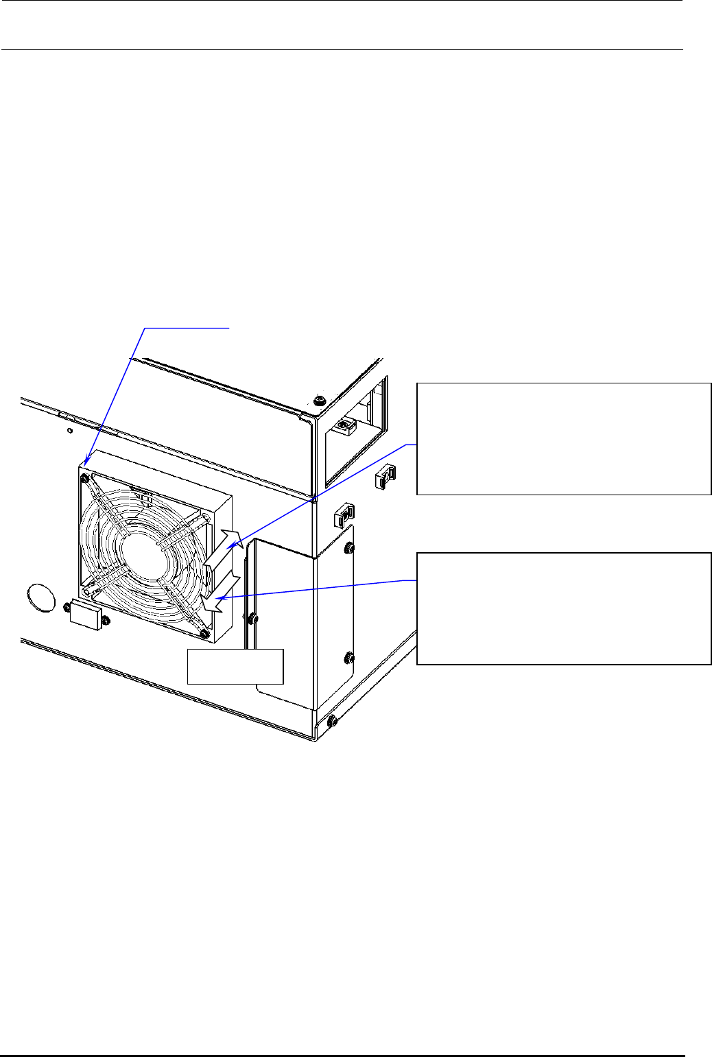
13-3-1-4. Rear Fan of Power Supply Unit
The air flow direction of the left rear fan of the power supply unit differs from that of the right rear
fan as follows.
• Right fan Exhaust direction
• Left fan Suction direction
For the POWER SUPPLY ASSY L (ST) (40098974) and POWER SUPPLY ASSY R (ST)
(40098950) used for the ST specification, remove the screws (SL4033591SC) shown below and
changing the air flow direction of the fan enables to swap the left fan with the right fan, and vice
versa. (For the fan for the EN specification, the fan mounting position cannot be changed since
different parts are used.)
AIR FLOW
40093150 POWER SUPPLY ASSY R (EN)
40098950 POWER SUPPLY ASSY R (ST)
EN specification:
Right: Fan exhaust
ST specification:
40093149 POWER SUPPLY ASSY L (EN)
40098974 POWER SUPPLY ASSY L (ST)
EN specification:
ST specification:
Left: Fan suction
SL4033591SC
×
2 pcs.
Figure 13-3-1-4-1 Left and Right of Power Supply Unit
Rev. 1.00
FX-3R Maintenance Guide
13-16
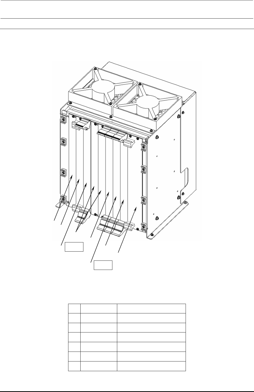
13-4. Control Unit
13-4-1. Structure of Control Unit
Figure 13-4-1-1 shows the board layout drawing of the control unit. Check that the boards are
mounted correctly while referring to these figures.
c
h
g
e POS2
h
f
e POS1
d
Figure 13-4-1-1 Board Layout Drawing (FX-3R)
Table 13-4-1-1 Boards Used for Control Unit
Part No. Part name
c
40107342 CPU BOARD
d
40048066 ETHER MAIN BOARD
e
40044540 POSITION BOARD
f
40048003 cPCI-8994
g
40047528 IP-X5 PCB ASM
h
E1649729000 BLANK PANEL B
Rev. 1.00

FX-3R Maintenance Guide
13-17
Rev. 1.00
13-4-2. CPU Board (40107372)
[Functions]
This is a circuit board that controls the equipment totally. This circuit board is connected to other
circuit boards by the Compact PCI (hereafter referred to as “cPCI”) bus.
[DIP switch settings]
This CPU board is used with the dip switch settings made before shipment.
[Meaning of LED]
PW: Shows the power supply status using the lighting status.
Lit in green.............Normal operation status
Flashing in green...Standby status
Off..........................Shutdown status
HDD: Flashes in green when accessing to the SSD.
RESET: Push switch with LED. This switch functions as the reset switch. The LED functions as
the Power ON LED.
Do not press this switch.
Lit in green.............Shows that the power is supplied.
Off..........................Shows that the power is not supplied.
[Replacement of battery]
A backup battery is mounted on the CPU board to save the BIOS settings.
Replace the battery at reference intervals of 5 years.
After the battery has been replaced, it is necessary to set up the BIOS.
[Adjustment items after replacement]
After the CPU board has been replaced, it is necessary to set up the BIOS.
Make the settings while referring to section 12-2-2, Setting Up the BIOS.