fx3r.pdf - 第100页
FX-3R Maintenance Guide 8-18 8-3-6. Replacing the ETF Incorr ect Insertion Detection Sensor 1) In the FX-3R, the sensors are arranged as shown in the Figure below. To remove the sensor together with the bracket, the sens…
FX-3R Maintenance Guide
8-17
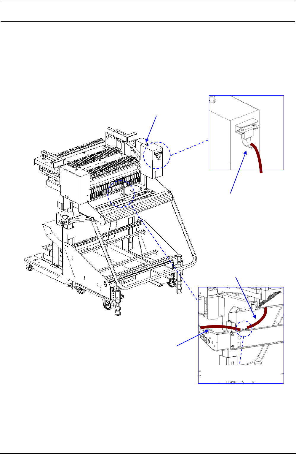
8-3-5. Replacing the Connector for Off-line Setup
1) Disconnect the connector for the off-line setup from the E trolley cover R.
2) Disconnect the connector connecting the cable of the connector for the off-line setup and the
relay cable to the electric bank PCB. After that, replace the connector for the off-line setup.
3) Reassemble the components in the reverse order of disassembly.
Rev. 1.00
40084841
EF setup cable 1 bracket
assembly
40084837
EF setup cable 2
assembly
40084841
EF setup cable 1 bracket
assembly
Connected at fixing base
40084666
E trolley cover R
Figure 8-3-5-1 Replacement of Connector for Off-line Setup
FX-3R Maintenance Guide
8-18
8-3-6. Replacing the ETF Incorrect Insertion Detection Sensor
1) In the FX-3R, the sensors are arranged as shown in the Figure below.
To remove the sensor together with the bracket, the sensor height needs to be adjusted.
To replace only the sensor, start the work from step 4).
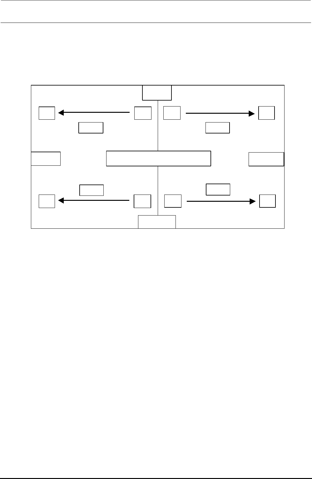
マウンタ上面図
LF
RF
RRLR
REAR
FRONT
LEFT
RIGHT
受投
受投
受 投
受 投
Rec.
Rec.
Rec.
Rec.
Emit Emit
Emit Emit
Top view of mounter
Figure 8-3-6-1 ETF Incorrect Insertion Detection Sensor Layout Drawing
2) Replace the sensor of the bracket assembly you have removed.
Rev. 1.00
FX-3R Maintenance Guide
8-19
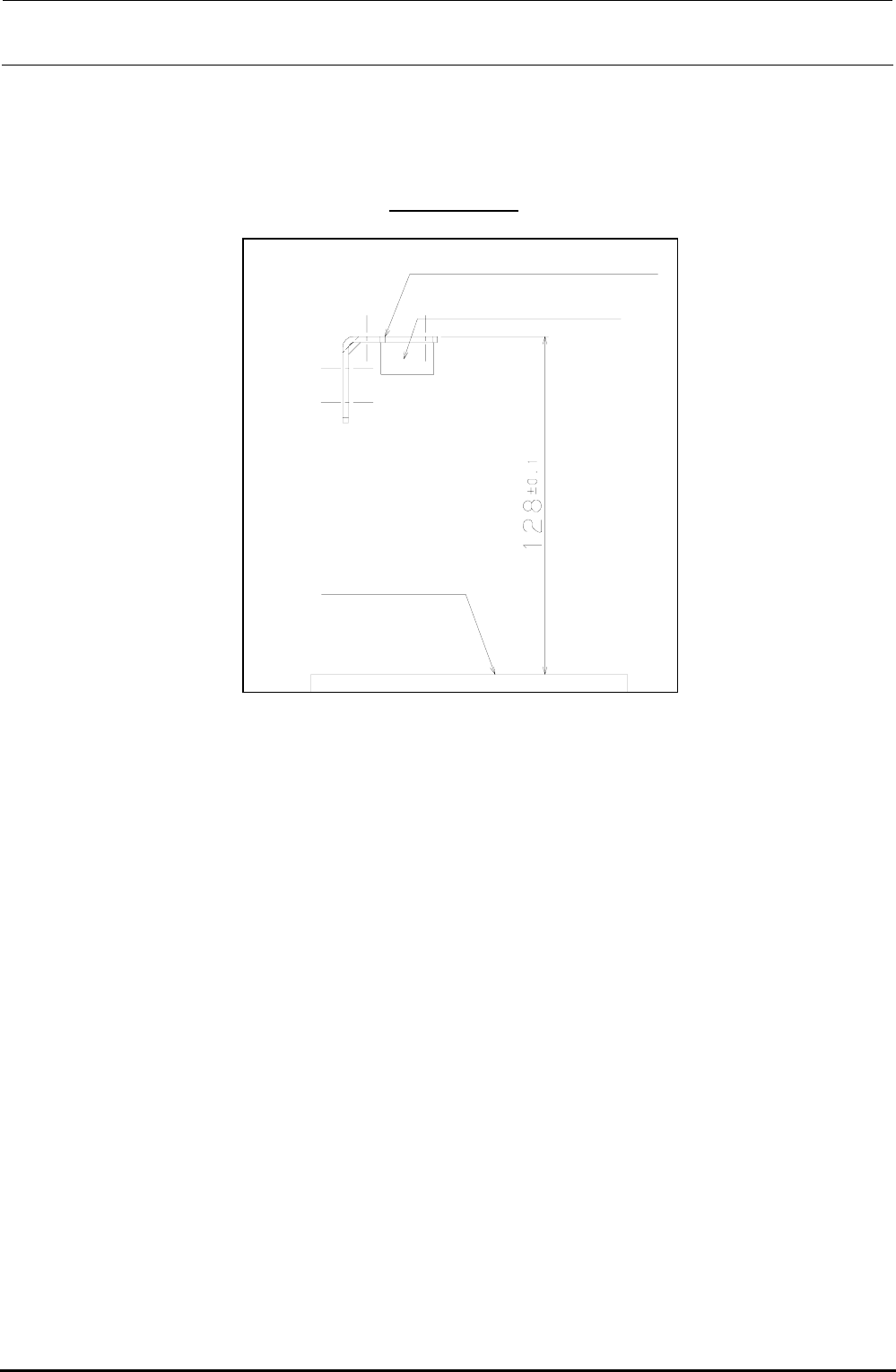
3) Adjust the height of the sensor you have replaced.
Adjust the top surface of the EFDS bracket to a height of 128 ± 0.1 mm from the top surface of
the bracket.
However, the height difference of the left and right EFDS brackets that become a pair (light
receiving and light emitting) must be
0.1 mm or less.
EFDS bracket L/R
ETF detection sensor
Top surface of bank
Figure 8-3-6-2 Height Adjustment of ETF Incorrect Insertion Detection Sensor
4) Adjust the optical axis.
c Connect the connector of each sensor to the specified position and turn ON the power to the
main unit.
d Move the sensor on the light emitting side or light receiving side to adjust the optical axis.
When the optical axis is adjusted correctly, both the red and green LEDs on the light
receiving side are lit.
(The red LED is the RUN indicator while the green LED is the STABILITY indicator.)
Rev. 1.00