fx3r.pdf - 第107页
FX-3R Maintenance Guide 9-2 <Setting Procedure> [ U ] button [ V ] button [LED] panel [SET] button Figure 9-1-1-1 Digital Pressure Switch 1) Setting the display mode and hysteresis mode c Keep the button pressed fo…
FX-3R Maintenance Guide
9-1
DANGER
To prevent any trouble caused by accidental machine start, always
shut-down the power before starting the maintenance and
adjustment work.
[9] PNEUMATIC UNITS
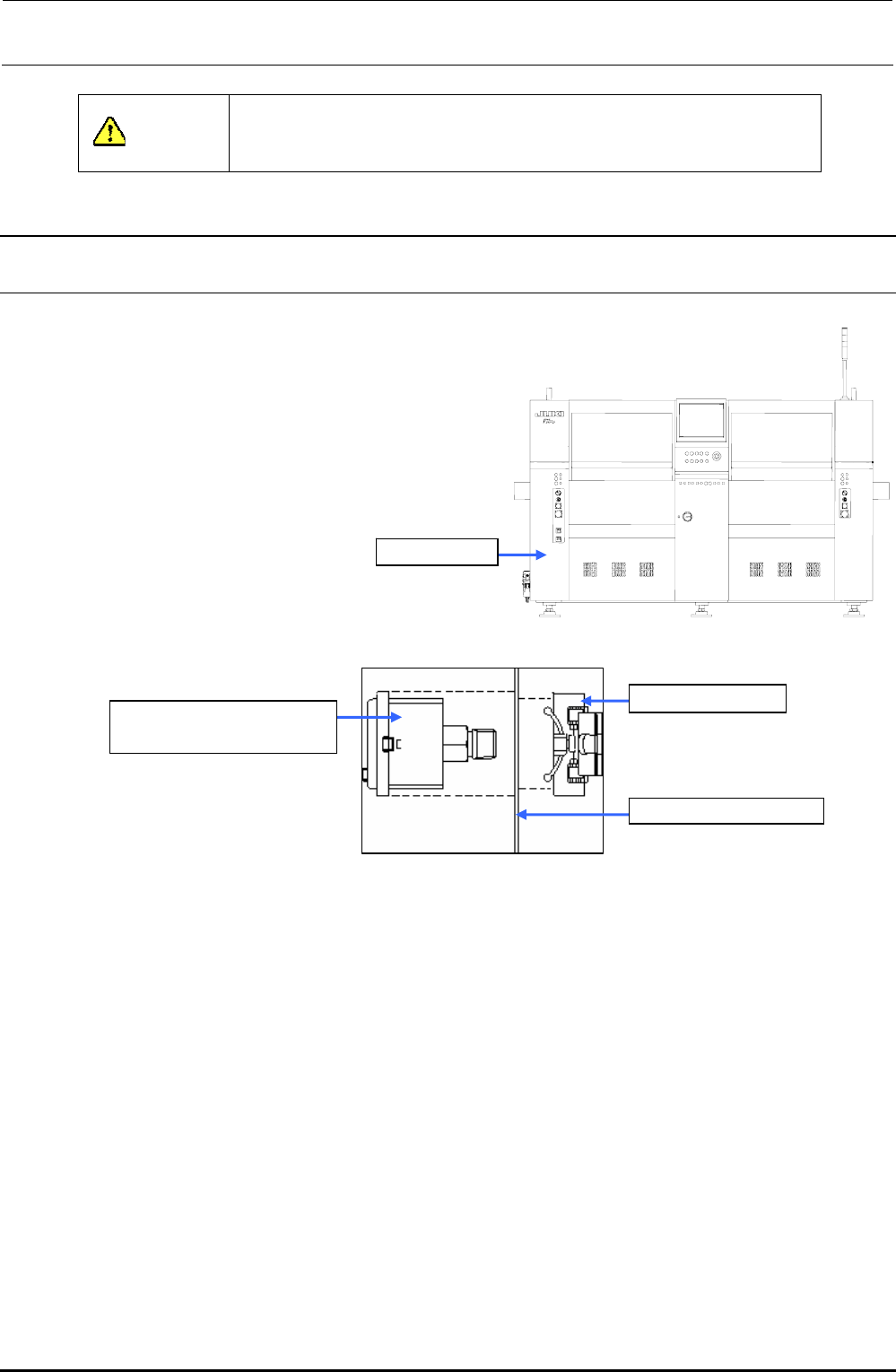
9-1. Replacing the Digital Pressure Switch (Positive Pressure)
1) Close the hand valve at the lower left portion
of the main unit.
2) Remove the screws (2 locations) to open the
cover SB_A (open/close cover).
3) Disconnect the φ6 air tube and connector
from the digital pressure switch.
4) Detach the digital pressure switch with the
fixing resin on the back of the bank pressure
bracket C kept pushed.
Cover SB_A
5) Reassemble the components in
the reverse order of disassembly.
Figure 9-1-1 Cover SB_A (Front Side)
40045958
DIGITAL PRESSURE SW
Resin fixing part
Bank switch bracket C
Figure 9-1-2 Digital Pressure Switch
9-1-1. Adjusting the Digital Pressure Switch (Positive Pressure)
After the digital pressure switch has been replaced, make the setting as shown below.
Threshold value of pressure switch: 0.400MPa
Hysteresis: 0.050MPa
Display color mode: Green when the pressure switch is turned ON.
Operation mode: Hysteresis mode
Pressure switch output form: Normally open
(Turned ON when the value is the threshold value or more.)
Response time: 2.5ms or less
Auto preset setting: Manual setting
Follow the steps to make the setting.
Rev. 1.00
FX-3R Maintenance Guide
9-2
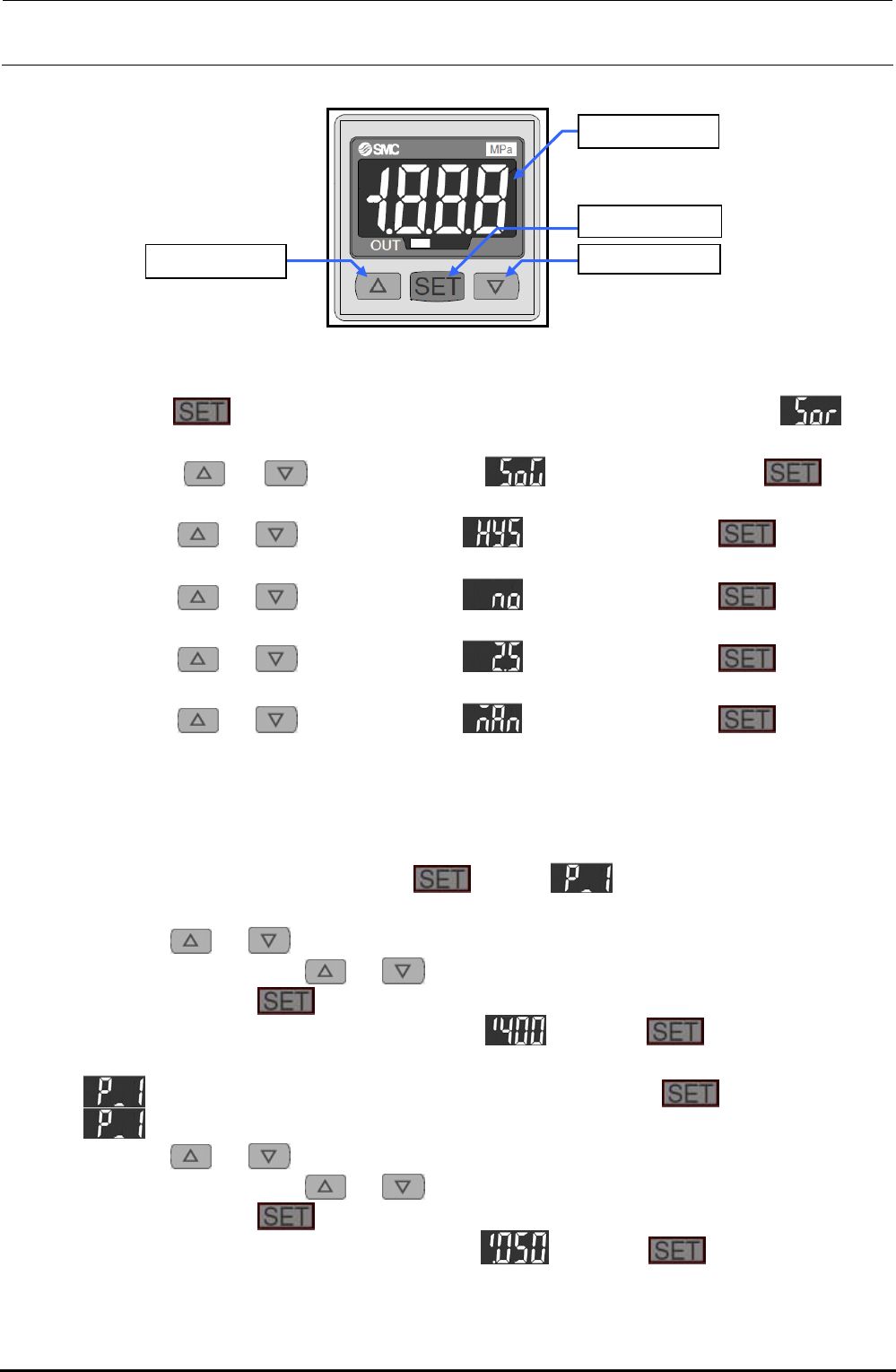
<Setting Procedure>
[U] button
[V] button
[LED] panel
[SET] button
Figure 9-1-1-1 Digital Pressure Switch
1) Setting the display mode and hysteresis mode
c Keep the
button pressed for 2 sec. or longer. The display will become . (The
operation enters the display color setting mode.)
d Press the
or button to display . After that, press the button.
(When the switch is turned ON, this is displayed in green.)
e Press the
or button to display . After that, press the button. (The
operation enters the hysteresis setting mode.)
f Press the
or button to display . After that, press the button. (The
normally open operation is set.)
g Press the
or button to display . After that, press the button. (The
response time is set at 2.5 ms or less.)
h Press the
or button to display . After that, press the button. (The
manual set mode is set.)
i The numeric value is displayed in this step, and then the operation is returned to the
measurement mode.
2) Setting a detection level (threshold value and hysteresis)
c In the measurement mode, press the
button. and current threshold value are
displayed alternately.
d Press the
or button. The numeric value at the least significant digit starts flashing.
Subsequently, press the
or button to increase or decrease the numeric value.
e When pressing the
button, the flashing digit moves left.
f Perform operation steps d and e to display
. Keep the button pressed for 2
sec. or longer. (The threshold value is then set to “0.400 MPa”.)
g
and current set value are displayed alternately. Press the button.
h
and current hysteresis value are displayed alternately.
i Press the
or button. The numeric value at the least significant digit starts flashing.
Subsequently, press the
or button to increase or decrease the numeric value.
j When pressing the
button, the flashing digit moves left.
k Perform operation steps h and j to display
. Keep the button pressed for 2
sec. or longer. (The hysteresis value is then set to “0.050 MPa”.)
l The operation is then returned to the measurement mode. The settings are then completed.
Rev. 1.00
FX-3R Maintenance Guide
9-3
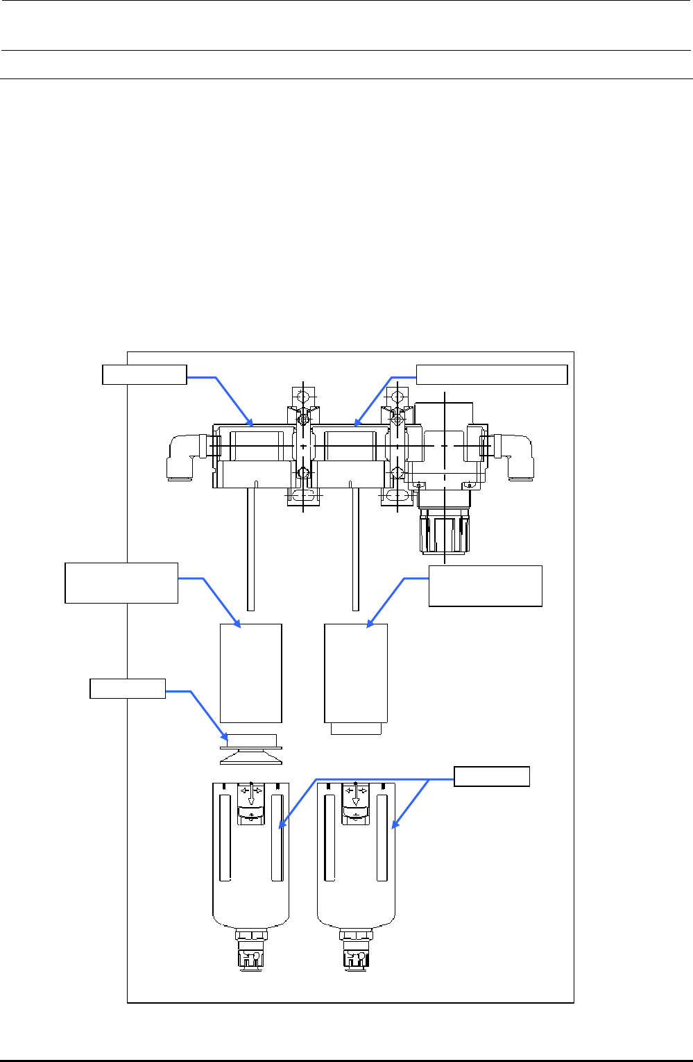
9-2. Replacing the Filter Element
1) Turn the filter element main unit 45( clockwise or counterclockwise to pull it out downward while
lowering the slide part.
2) When replacing the filter element B on the air filter side, turn the resin part fixing the filter
element B counterclockwise to detach it.
3) When replacing the filter element on the micromist separator side, turn the filter element
counterclockwise to detach it.
4) Reassemble the components in the reverse order of disassembly.
CAUTION Before replacing the filter element, always close the knob of the finger valve.
The filter element must be replaced when it has been used for two years or when
pressure drop reaches 0.1 MPa (1kgf/cm
2
).
Air filter Micromist separator
PF901006000
Filter element
PF901010000
Filter element
Resin part
Slide part
Figure 9-2-1 Filter Element
Rev. 1.00