fx3r.pdf - 第175页
FX-3R Maintenance Guide 13-6 Rev . 1.00 Table 13-3-1-2-1 Power Supply Unit (Parts List) No. Parts No. Name Qty. Remarks 1 HA00524000E Circuit protector (12A) 1 CP7 2 HA00524000F Circuit protector (4A) 1 CP8 (EN specifica…
FX-3R Maintenance Guide
13-5
(EN specifications)
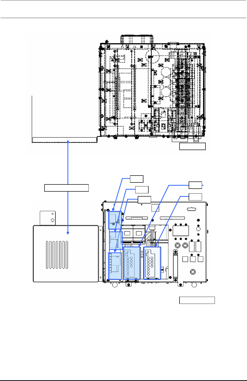
[Front view]
PSU front cover
[Top view]
PS5
PS1
PS2
PS3
PS4
Figure 13-3-1-2-2 Block Diagram of the Power Supply Unit (EN)
∗ The above Figure shows the power supply unit with the PSU front cover shifted left.
Rev. 1.00
FX-3R Maintenance Guide
13-6
Rev. 1.00
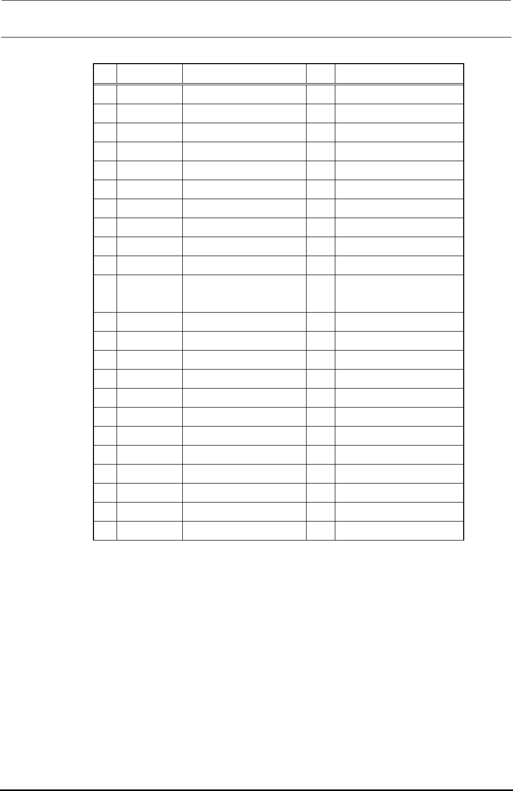
Table 13-3-1-2-1 Power Supply Unit (Parts List)
No. Parts No. Name Qty.
Remarks
1 HA00524000E Circuit protector (12A) 1 CP7
2 HA00524000F Circuit protector (4A) 1 CP8 (EN specification only)
3 HA00524000G Circuit protector (20A) 1 CP6
4 HA00527000A Circuit protector (40A) 1 CP4
5 HA00527000C Circuit protector (25A) 1 CP12
6 HA00542000C Circuit protector (10A) 2 CP2, CP11
7 HA00542000D Circuit protector (15A) 1 CP3
8 HA005570000 Circuit protector (10A) 1 CP5
9 HA005600000 Circuit protector (40A) 1 CP1
10 HB001100000 Relay 1 RL4
11 HB00128000C Relay 5
RL1 (ST specification only)
RL5 to 8
12 HB001740000 Relay 1 RL1 (EN specification only)
13 HB001540000 Relay 2 RL2, 3
14 HB001540010 Relay socket 2 For RL2, 3
15 HM00033000A AC FAN 1
16 HX006750000 Power supply +24V/600W 2 PS2,PS5
17 HX00542000B Power supply +24V/100W 1 PS4 (EN specification only)
18 HX00543000A Power supply +24V/300W 1 PS3
19 KX000000150 Power supply +6V/75W 1 PS1
20 40047522 POWER PCB ASM 1
21 40047524 Zθ POWER PCB ASM 1
22 HA005300000 Contactor 2 K1, 2 (EN specification only)
23 HA005300020 Terminal cover 2 For K1, 2 (EN specification only)
FX-3R Maintenance Guide
13-7
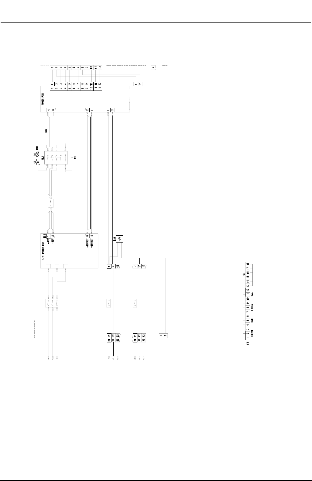
13-3-1-3. Connection Diagram for the Power Supply Unit
U
3
4
V
3
4
W
3
4
A
C
3
4
V
I
N
P
U
T
1
2
3
1
2
3
L
O
A
D
T
B
P
1
0
2
P
O
W
E
R
U
N
I
T
I
N
S
I
D
E
TB1
U34
V34
W34
TB2
TB3
I
N
O
U
T
TB3
+48VRET
+4
8VRET
10
0L
AC100V
INPUT
CN06
2
I
N
O
U
T
I
N
O
U
T
10
0VB1
0VB1
CN0
62
TB
CN0
63
P
1
0
1
P
1
0
3
P
1
0
3
P
1
0
3
P
1
0
3
P
1
1
1
P
1
0
4
P
1
0
5
TB1
P
1
0
8
P
1
0
9
P
1
1
0
注1.端子台TBのジャンパ接続は上図の通り。
(
100VA)
(0VA)
(
3-3A)
AC100V
INPUT
AC100V
OUTPUT
100N
FG
1
00L
100N
F
G
+48V
+48V
14
24
34
13
23
33
4443
A
1
A
2
+
2
4
V
A
(
2
-
2
B
)
SVON(N)
CN064
to
XY-RELAY
BOARD
(2-5C)
P
1
0
7
+48V
+24VD
+6V
+24VA
+24VB
+24VC
+48VR
ET
+24VDRET
+6VR
ET
+24VARET
+24V
BRET
+24VCRET
CN039
P
1
1
2
CN08
1
L
I
N
E
t
o
ATX-PO
WER
to
ETF-POWER
CN039PW
CN039
CP1(40A)
HA005600000
CP2(10A)
HA00542000C
CP3(15A)
HA00542000D
CP4(40A)
HA00527000A
Note 1. Jumper line connections on the terminal block TB are as shown in the diagram above.
Figure 13-3-1-3-1 Connection Diagram for the Power Supply Unit (1/3)
Rev. 1.00