fx3r.pdf - 第176页
FX-3R Maintenance Guide 13-7 13-3-1-3. Connection Diagram for the Pow er Supply Unit U 3 4 V 3 4 W 3 4 A C 3 4 V I N P U T 1 2 3 1 2 3 L O A D T B P 1 0 2 P O W E R U N I T I N S I D E TB1 U34 V34 W34 TB2 TB3 I N O U T T…
FX-3R Maintenance Guide
13-6
Rev. 1.00
Table 13-3-1-2-1 Power Supply Unit (Parts List)
No. Parts No. Name Qty.
Remarks
1 HA00524000E Circuit protector (12A) 1 CP7
2 HA00524000F Circuit protector (4A) 1 CP8 (EN specification only)
3 HA00524000G Circuit protector (20A) 1 CP6
4 HA00527000A Circuit protector (40A) 1 CP4
5 HA00527000C Circuit protector (25A) 1 CP12
6 HA00542000C Circuit protector (10A) 2 CP2, CP11
7 HA00542000D Circuit protector (15A) 1 CP3
8 HA005570000 Circuit protector (10A) 1 CP5
9 HA005600000 Circuit protector (40A) 1 CP1
10 HB001100000 Relay 1 RL4
11 HB00128000C Relay 5
RL1 (ST specification only)
RL5 to 8
12 HB001740000 Relay 1 RL1 (EN specification only)
13 HB001540000 Relay 2 RL2, 3
14 HB001540010 Relay socket 2 For RL2, 3
15 HM00033000A AC FAN 1
16 HX006750000 Power supply +24V/600W 2 PS2,PS5
17 HX00542000B Power supply +24V/100W 1 PS4 (EN specification only)
18 HX00543000A Power supply +24V/300W 1 PS3
19 KX000000150 Power supply +6V/75W 1 PS1
20 40047522 POWER PCB ASM 1
21 40047524 Zθ POWER PCB ASM 1
22 HA005300000 Contactor 2 K1, 2 (EN specification only)
23 HA005300020 Terminal cover 2 For K1, 2 (EN specification only)
FX-3R Maintenance Guide
13-7
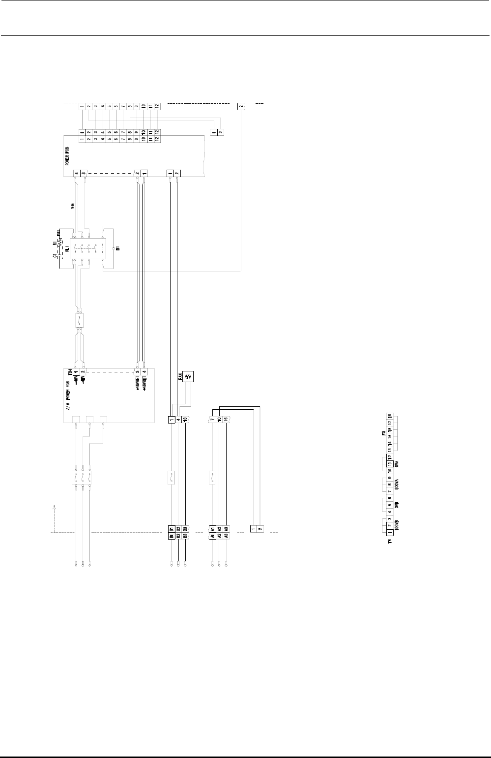
13-3-1-3. Connection Diagram for the Power Supply Unit
U
3
4
V
3
4
W
3
4
A
C
3
4
V
I
N
P
U
T
1
2
3
1
2
3
L
O
A
D
T
B
P
1
0
2
P
O
W
E
R
U
N
I
T
I
N
S
I
D
E
TB1
U34
V34
W34
TB2
TB3
I
N
O
U
T
TB3
+48VRET
+4
8VRET
10
0L
AC100V
INPUT
CN06
2
I
N
O
U
T
I
N
O
U
T
10
0VB1
0VB1
CN0
62
TB
CN0
63
P
1
0
1
P
1
0
3
P
1
0
3
P
1
0
3
P
1
0
3
P
1
1
1
P
1
0
4
P
1
0
5
TB1
P
1
0
8
P
1
0
9
P
1
1
0
注1.端子台TBのジャンパ接続は上図の通り。
(
100VA)
(0VA)
(
3-3A)
AC100V
INPUT
AC100V
OUTPUT
100N
FG
1
00L
100N
F
G
+48V
+48V
14
24
34
13
23
33
4443
A
1
A
2
+
2
4
V
A
(
2
-
2
B
)
SVON(N)
CN064
to
XY-RELAY
BOARD
(2-5C)
P
1
0
7
+48V
+24VD
+6V
+24VA
+24VB
+24VC
+48VR
ET
+24VDRET
+6VR
ET
+24VARET
+24V
BRET
+24VCRET
CN039
P
1
1
2
CN08
1
L
I
N
E
t
o
ATX-PO
WER
to
ETF-POWER
CN039PW
CN039
CP1(40A)
HA005600000
CP2(10A)
HA00542000C
CP3(15A)
HA00542000D
CP4(40A)
HA00527000A
Note 1. Jumper line connections on the terminal block TB are as shown in the diagram above.
Figure 13-3-1-3-1 Connection Diagram for the Power Supply Unit (1/3)
Rev. 1.00
FX-3R Maintenance Guide
13-8
Rev. 1.00
T
B
C
P
6
(
2
0
A
)
I
N
O
U
T
+
2
4
V
A
R
E
T
+
2
4
V
A
+
2
4
V
C
R
E
T
+
2
4
V
C
T
B
P202
P208
P205
P206 P207
CP5(10A)
CN1
AC(L
)
AC(N)
FG
IN OUT
N.C.
N.C.
+6VGND
+6V
TB4
P201
P203
P203
P204
+24VA
(1-4A)
+
2
4
V
A
(2-4C)
+
2
4
V
A
(2-4B)
+
2
4
V
A
(2-4B)
+24VBRET
+24VB
注1.端子台TBのジャンパ接続は上図の通り。
24
68
01
TB2
+
2
4
V
A
(2-2B)
TB
OK-F(N)
CN064
2
4
18
6
5
7
+
2
4
V
A
(2-2B)
3
2
4
18
6
5
7
TB
+
2
4
V
A
(2-2B)
3
TB5
OK-R(N)
CARRY SVON(N)
CN066
100VB3F
0VB3F
CN065
POWER UNIT INSIDE
to overa
ll
replacement
table(R)
to overa
ll
replacement
table(F)
to
XY-RELAY
BOARD
CP7(
12A)
TB1
AC(N)
FG
IN OUT
AC(L)
P210
P211
(1-5C)
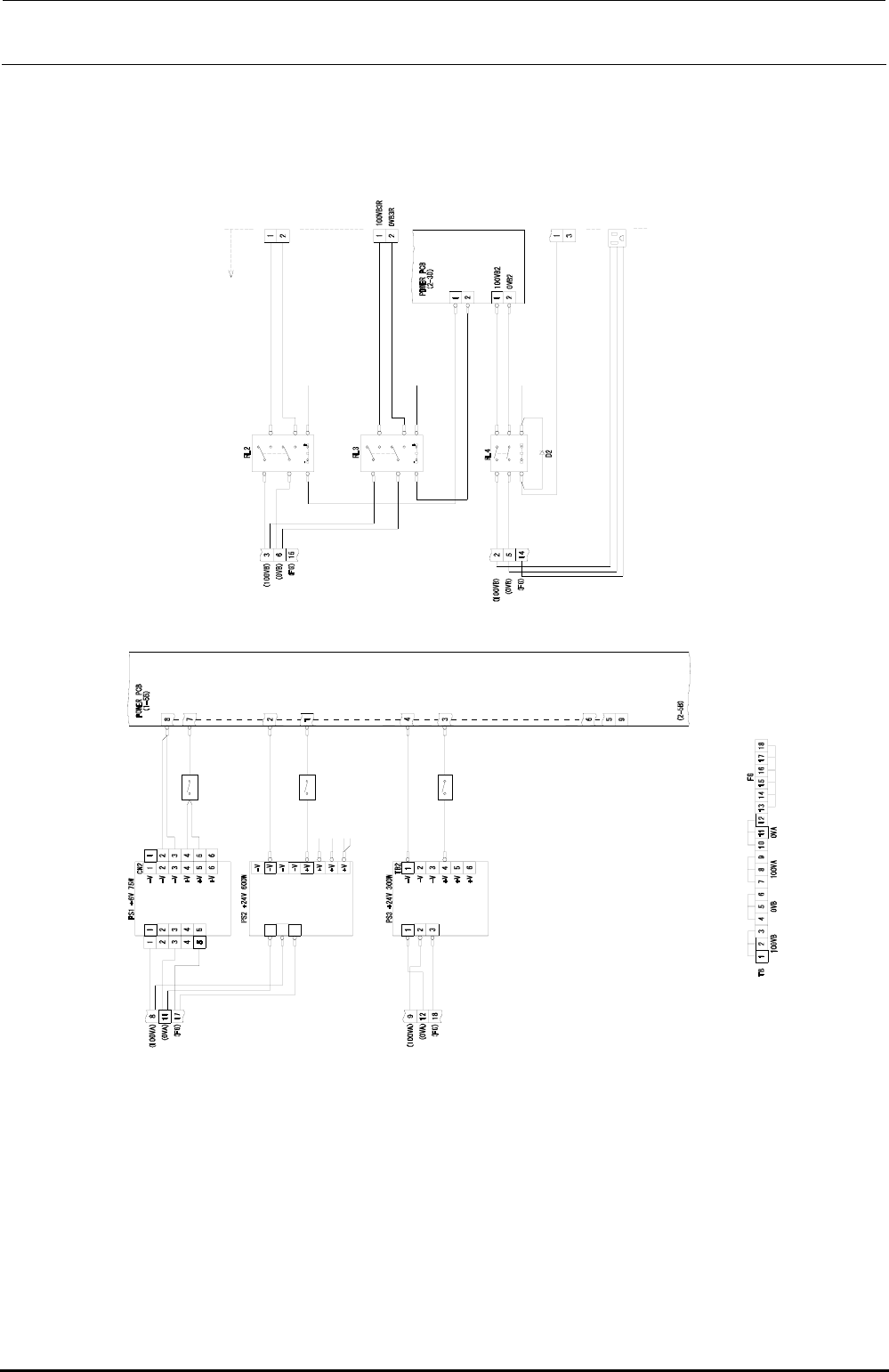
Figure 13-3-1-3-2 Connection Diagram for the Power Supply Unit (2/3)
P212
P215
P216
P217
P219
P218
P218
P222
P223
P224
P107
P221
N.C.
SC1
P225
Note 1. Jumper line connections on the terminal block TB are as shown in the diagram above.
HA00524000G
HA00524000E
HA005570000
N
FG
L
HX00
6750000