fx3r.pdf - 第183页
FX-3R Maintenance Guide 13-14 ∗ Note 1: Indicate the bracketed inscriptions by silk-screen printing. ∗ Note 2: Indicate the signal names of CN039 by silk-screen printing (excluding N. C.). ∗ Note 3: Connect the OK signal…
FX-3R Maintenance Guide
13-13
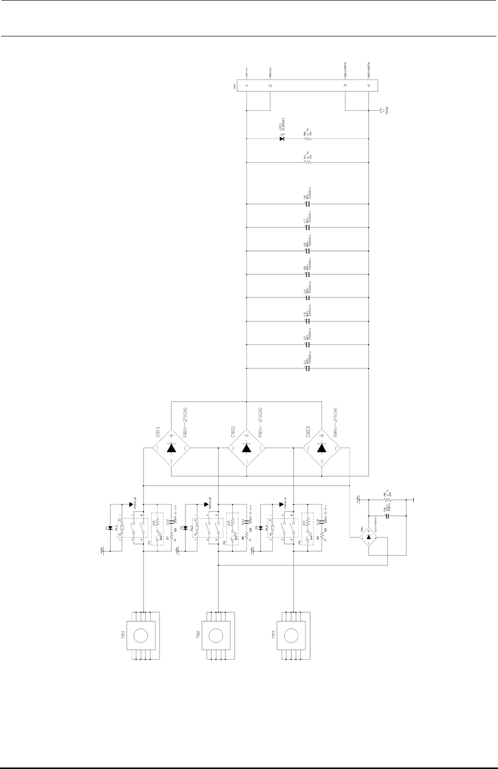
Figure 13-3-1-3-7 Connection Diagram for the Z/θ Power Supply Board
Rev. 1.00
FX-3R Maintenance Guide
13-14
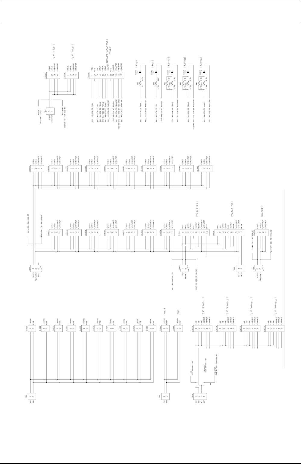
∗ Note 1: Indicate the bracketed inscriptions by silk-screen printing.
∗ Note 2: Indicate the signal names of CN039 by silk-screen printing (excluding N. C.).
∗ Note 3: Connect the OK signals of CN024 and 025 so that +24VARET patterns sandwich them.
∗ Note 3
∗ Note 3
Figure 13-3-1-3-8 Connection Diagram for the Power Supply Board
Rev. 1.00
FX-3R Maintenance Guide
13-15
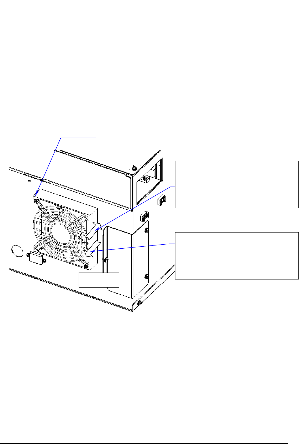
13-3-1-4. Rear Fan of Power Supply Unit
The air flow direction of the left rear fan of the power supply unit differs from that of the right rear
fan as follows.
• Right fan Exhaust direction
• Left fan Suction direction
For the POWER SUPPLY ASSY L (ST) (40098974) and POWER SUPPLY ASSY R (ST)
(40098950) used for the ST specification, remove the screws (SL4033591SC) shown below and
changing the air flow direction of the fan enables to swap the left fan with the right fan, and vice
versa. (For the fan for the EN specification, the fan mounting position cannot be changed since
different parts are used.)
AIR FLOW
40093150 POWER SUPPLY ASSY R (EN)
40098950 POWER SUPPLY ASSY R (ST)
EN specification:
Right: Fan exhaust
ST specification:
40093149 POWER SUPPLY ASSY L (EN)
40098974 POWER SUPPLY ASSY L (ST)
EN specification:
ST specification:
Left: Fan suction
SL4033591SC
×
2 pcs.
Figure 13-3-1-4-1 Left and Right of Power Supply Unit
Rev. 1.00