fx3r.pdf - 第188页
FX-3R Maintenance Guide 13-19 Rev . 1.00 13-4-4. cPCI-8994 Board (40048003) [Functions] This cPCI-8994 board is a communication board with the LNC60, a laser sensor. The cPCI-8994 board performs the communication between…
FX-3R Maintenance Guide
13-18
13-4-3. Position Board (40044540)
[Functions]
This POSITION board is applicable to the CPCI bus and intended to control servomotors
through the SSCNET III, Mitsubishi Electric’s high-speed synchronous communication network.
The POSITION board can control up to 32-axis servomotors per board.
The POSITION board is connected to the servo amplifier of each axis through daisy chain
connections of optical fiber cables.
c A command is received from the CPU board software to control the XYZθ-axis servomotor.
d The home position sensor and limit sensor of each axis are detected.
e An alarm is detected that occurs in the servo amplifier or magnescale.
f The emergency stop switch is detected to stop the XY-axis and Zθ-axis.
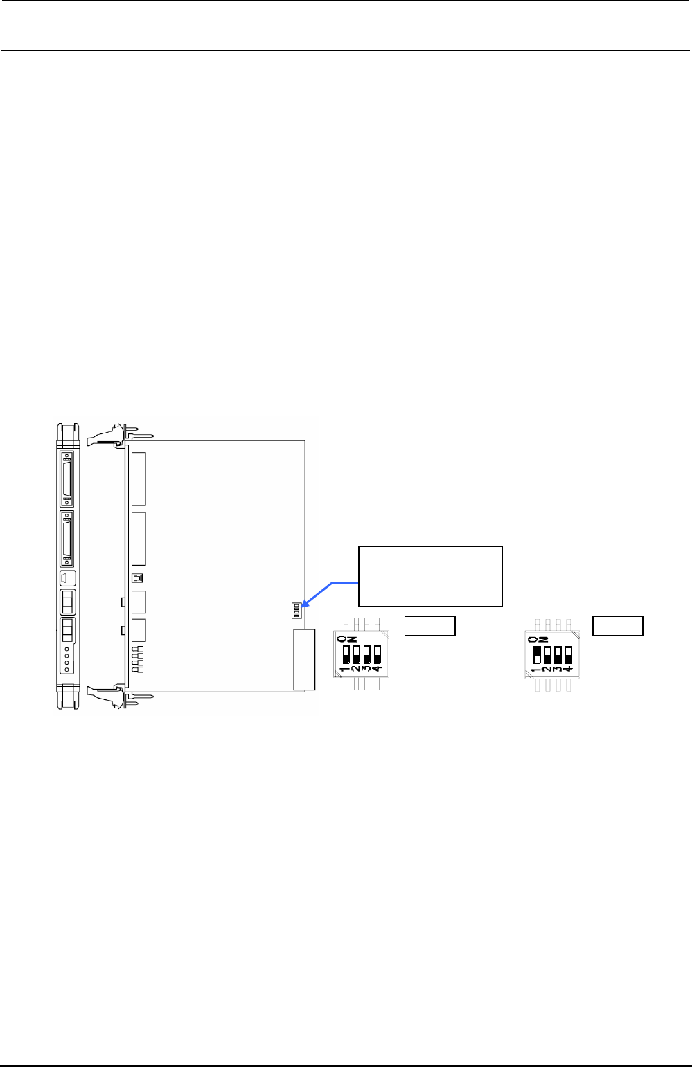
[Switch settings]
Since the FX-3R uses two position boards, the settings may vary depending on the position
board, which has been replaced.
The settings are shown below. ( portions show the switch positions.)
Change the settings
with the POS1 or
POS2 switch.
POS1
SW-1 :OFF
SW-1 :OFF
SW-1 :OFF
SW-1 :OFF
POS2
SW-1 :ON
SW-1 :OFF
SW-1 :OFF
SW-1 :OFF
POS1 POS2
Figure 13-4-3-1 DIP switch on Position Board
∗ POS1 switch is used for the left station while POS2 switch is used for the right station.
[Meaning of LED]
Operation indicator LED (Green): Lights up when the power is turned ON, flashes when the
system is started up, goes off when the power is shut-down.
Error indicator LED (Red): Off during normal operation, Lights up if an error occurs.
[Adjustment items after replacement]
There are no particular adjustment items.
Rev. 1.00

FX-3R Maintenance Guide
13-19
Rev. 1.00
13-4-4. cPCI-8994 Board (40048003)
[Functions]
This cPCI-8994 board is a communication board with the LNC60, a laser sensor.
The cPCI-8994 board performs the communication between the LNC60 and CPU board through
the IEEE1394a-2000 communication standards (also called “FireWire 400”).
Additionally, the power (DC+12V) is supplied to the LNC60 through the communication cable.
In addition to four IEEE 1394 ports, this board contains four RS232C ports to perform the
communication with the CVS or barcode reader.
[DIP switch settings]
There are no DIP switches on the cPCI-8994 board.
[Meaning of LED]
There are no LEDs on the cPCI-8994 board.
[Adjustment items after replacement]
There are no particular adjustment items.
FX-3R Maintenance Guide
13-20
13-4-5. ETHER-MAIN Board (40048066)
[Functions]
This ETHER-MAIN board is a host board used to communicate with the ETHER-SLAVE board
through the Ethernet.
The board is connected to the Compact PCI (hereafter referred to as “cPCI”) bus so as to
access each peripheral I/O from the CPU board. Additionally, the MS parameter backup data is
saved into the FLASH ROM.
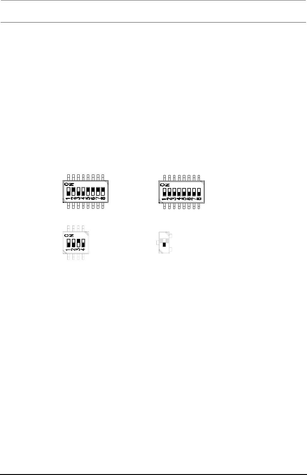
[DIP switch settings]
The DIP switches have been set properly at the delivery of the machine. When setting the board
in the control unit, check the DIP switch settings. ( portions show the switch positions.)
SW2-1 :OFF
SW2-2 :ON
SW2-3 :OFF
SW2-4 :OFF
SW2-5 :ON
SW2-6 :ON
SW2-7 :ON
SW2-8 :ON
SW4-1 :OFF
SW4-2 :OFF
SW4-3 :OFF
SW4-4 :OFF
SW4-5 :OFF
SW4-6 :OFF
SW4-7 :OFF
SW4-8 :OFF
SW1-1 :OFF
SW1-2 :OFF
SW1-3 :ON
SW1-4 :OFF
SW5:OFF
Note) SW5 is not mounted
on the board
(40048066).
Figure 13-4-5-1 DIP switches on ETHER-MAIN Board Assembly
[Meaning of LED]
7-segment LED: Shows the operation status of this board.
RUN LED: Lights up when the power is supplied.
EN1: Shows Link/Act of EN1. EN1 → Left station
EN2: Shows Link/Act of EN2. EN2 → Right station
EN3: Shows Link/Act of EN3. EN3 → XY-RELAY board – BASE CARRY board –
FEEDER board
EN4: Shows Link/Act of EN4.
[Adjustment items after replacement]
After that, follow the steps below to update the FLASH memory.
c Select [Options] and [Change User Group], and then select [Serviceman].
d Select [Maintenance] and [MS Parameter Setup].
e Select [Upgrade] and [Ether Main].
f Clicking [Exec.] will start the upgrading process.
Rev. 1.00