fx3r.pdf - 第199页
FX-3R Maintenance Guide 13-30 13-5. X-Y Unit The X-Y unit is composed of AC servo amplifier t hat drives the X/Y-axes and a magnescale that detects the movement position. 13-5-1. Structure of X-Y Unit For the AC servo am…
FX-3R Maintenance Guide
13-29
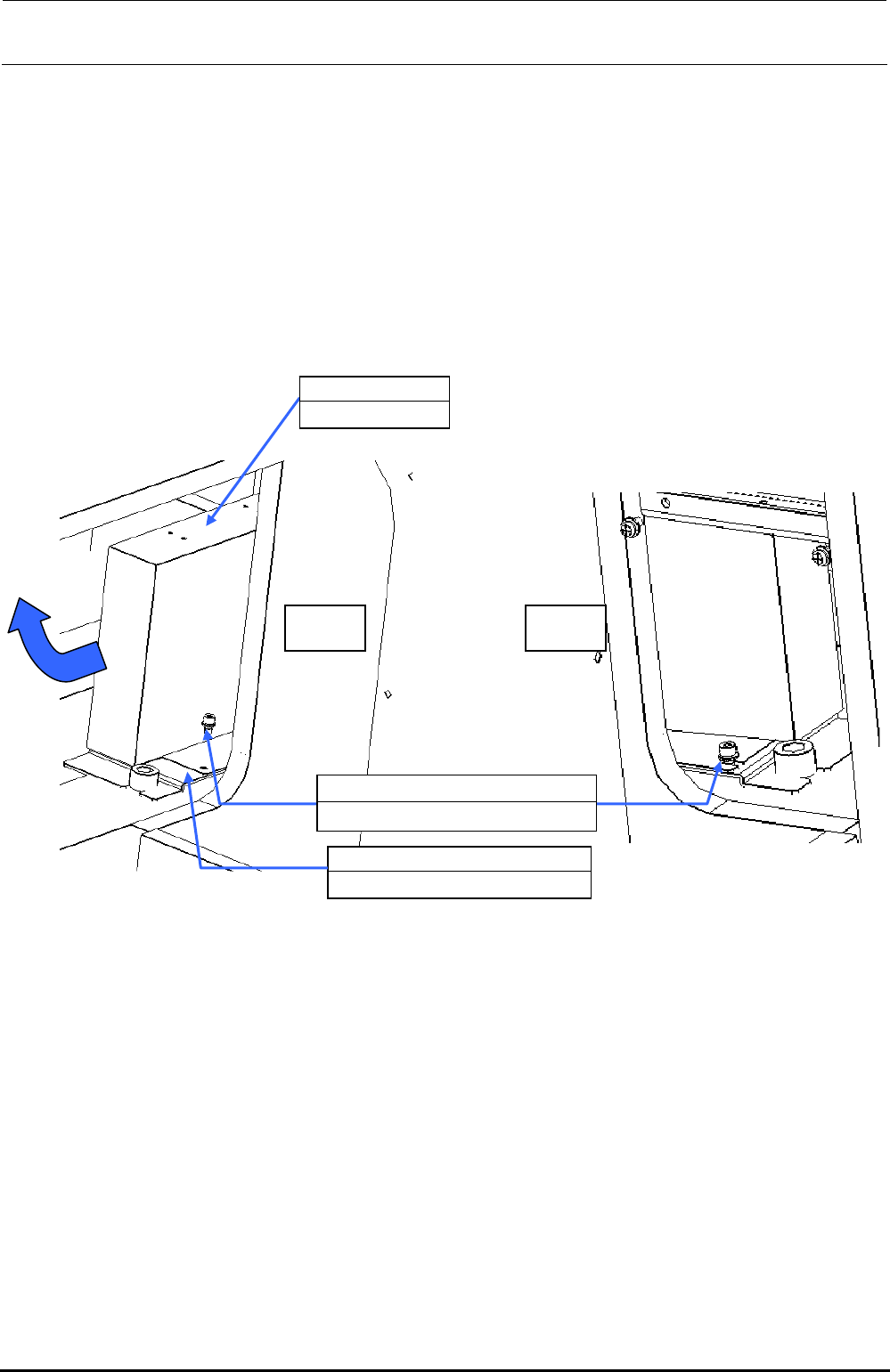
[Replacement procedure]
c Before starting the replacement work, always turn OFF the main power, main circuit
breaker, and main switch.
d The battery unit is located on the left in front of the base frame center and below the ATX
power supply (40048006). Remove SL6041092TN (1 pc.) on the left and loosen
SL6040892TN (1 pc.) on the right to detach the battery unit together with the BATTERY
SUPPORT PLATE (40092122).
e Remove four inch screws (40048047) to detach the battery unit from the BATTERY
SUPPORT PLATE (40092122).
Additionally, disconnect the cables from the ATX power supply.
f Replace the battery unit with a new one. Reassemble the parts and components in the
reverse order of disassembly.
Left Right
40048007
Battery unit
40092122
BATTERY SUPPORT PLATE
SL6040892TN
×
2
SEMS cap bolt with washer M4×8
Figure 13-4-10-2 Detaching the Battery Unit
Rev. 1.00
FX-3R Maintenance Guide
13-30
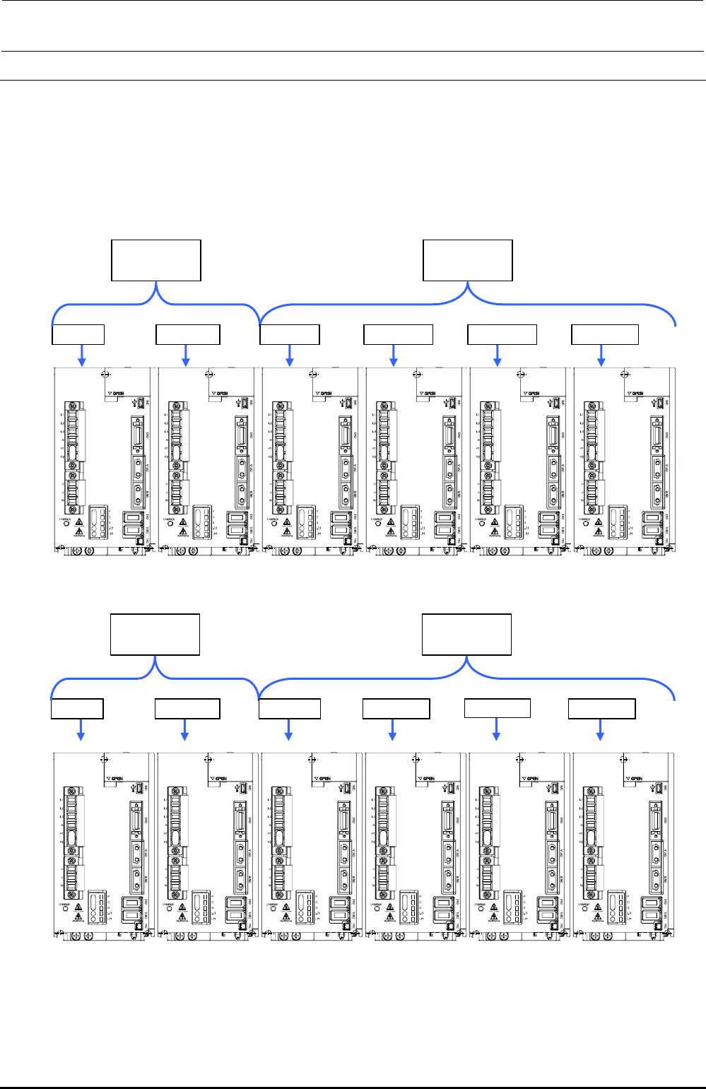
13-5. X-Y Unit
The X-Y unit is composed of AC servo amplifier that drives the X/Y-axes and a magnescale that
detects the movement position.
13-5-1. Structure of X-Y Unit
For the AC servo amplifiers, four AC servo amplifiers that drive the X-axis and eight AC servo
amplifiers that drive the Y-axis (twelve amplifiers in total) are mounted.
40104695
X-axis AMP
40104696
Y-axis AMP
X (LF) X (LR) YL (LF) YR (LF) YL (LR) YR (LR)
Figure 13-5-1-1 Structure of X-Y Unit (Left Side inside Base Frame)
40104695
X-axis AMP
40104696
Y-axis AMP
X (RF) X (RR) YL (RF) YR (RF) YL (RR) YR (RR)
Figure 13-5-1-2 Structure of X-Y Unit (Right Side inside Base Frame)
Rev. 1.00
FX-3R Maintenance Guide
13-31
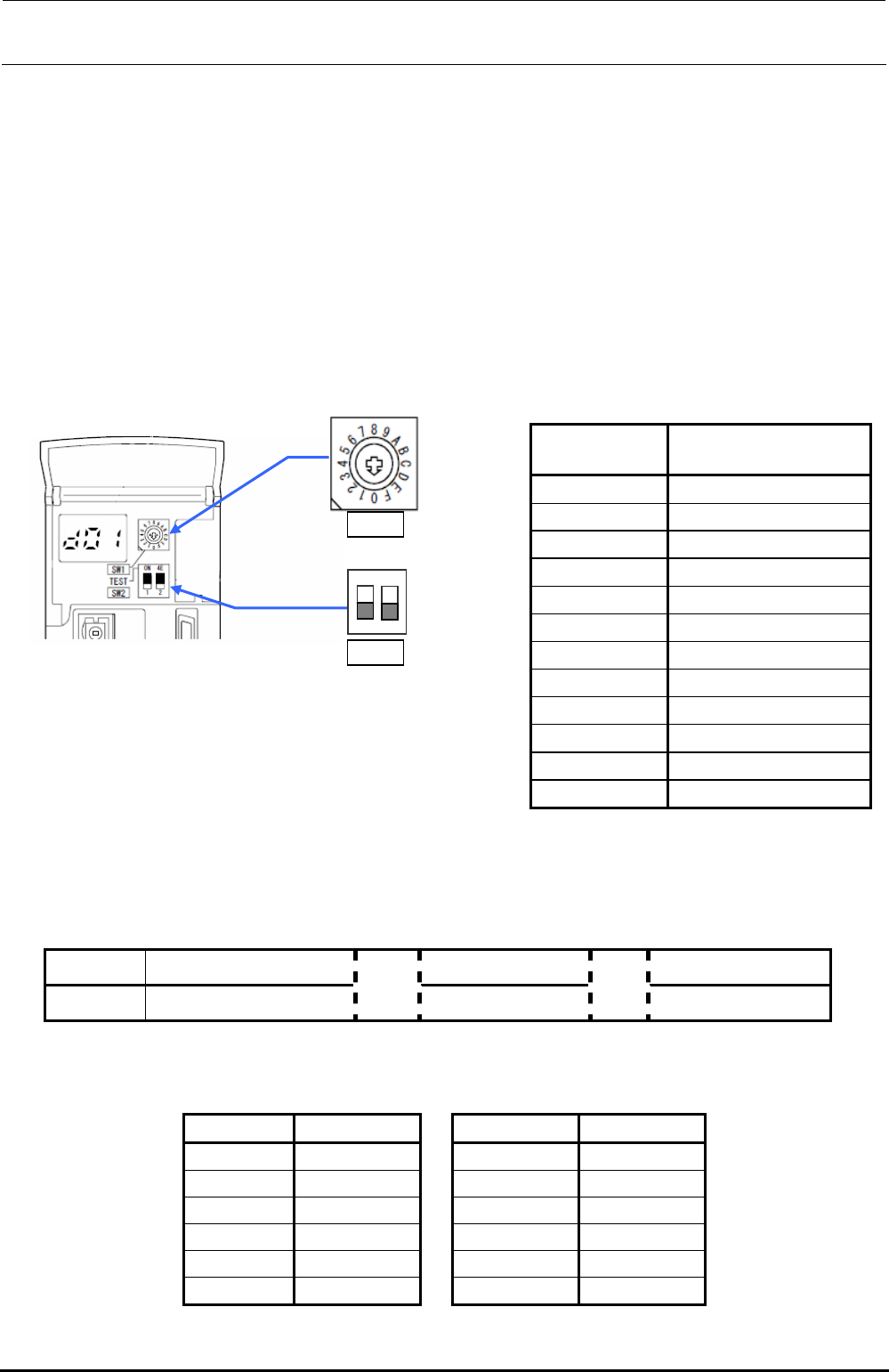
[Adjustment items after replacement]
When replacing the servo amplifier, it is necessary to set the axis selection with the rotary switch
(SW1) on the servo amplifier of each axis.
Open the front cover of the servo amplifier and turn the rotary switch (SW1) for the axis selection
so that the arrow mark indicates the following set value.
Make sure that the DIP switch (SW2) is OFF.
After the adjustment has been completed, turn ON the power to the main unit and turn it OFF.
After that, restart the operation.
Note. When the main unit is started up for the first time after the servo amplifier has been
replaced, do not perform the origin return.
Table 13-5-1-1 Rotary Switch Settings
Servo amplifier
Axis selection switch
set values
X (LF) 0
X (LR) 1
YL (LF) 0
YR (LF) 1
YL (LR) 2
YR (LR) 3
X (RF) 0
X (RR) 1
YL (RF) 0
YR (RF) 1
YL (RR) 2
YR (RR) 3
1
2
ON
SW1
SW2
13-5-2. Display Indication of XY Servo Amplifier
A 7-segment LED that indicates the status is mounted on the front of the XY servo amplifier.
Normally, this LED shows the status as described below.
Table 13-5-2-1 7-Segment LED Indication
Indication Ab C# d#
Contents Initialization is in progress.
→
Servo OFF
→
Servo ON
∗ Axis No. is shown in the “#” portion. (See also the Table below.)
Table 13-5-2-2 7-Segment LED Indication
Axis Axis No.
Axis Axis No.
X (LF)-axes 01
X (RF)-axes 01
X (LR)-axes 02
X (RR)-axes 02
YL (LF)-axes 01
YL (RF)-axes 01
YR (LF)-axes 02
YR (RF)-axes 02
YL (LR)-axes 03
YL (RR)-axes 03
YR (LR)-axes 04
YR (RR)-axes 04
Rev. 1.00