fx3r.pdf - 第218页
FX-3R Maintenance Guide 13-49 13-9. Covers 13-9-1. Structure of Operation Unit The operation unit is composed of the following four kinds of boards. c 40047520 Operation board front assembly d 40047542 Operation board re…

FX-3R Maintenance Guide
13-48
Rev. 1.00
13-8-1-1-4. LED Indications
The following Table shows the meanings of the LEDs mounted on the HEAD MAIN PCB ASM.
No. Lighting conditions
LD4 (Note)
Ether (ch2) Speed 100Mbps: Lit 10Mbps: Unlit
LD5 (Note)
Ether (ch2) Full Dup/Col Full-duplex: Lit Collision occurs.: Flashing
LD6 (Note)
Ether (ch2) Link/Act Linked: Lit Data send/receive: Flashing
LD7
Ether (ch1) Speed 100Mbps: Lit 10Mbps: Unlit
LD8
Ether (ch1) Full Dup/Col Full-duplex: Lit Collision occurs.: Flashing
LD9
Ether (ch1) Link/Act Linked: Lit Data send/receive: Flashing
LD25
Not used: (Lights up when the home position sensor of the LZ1-axis is turned ON.)
LD26
Not used: (Lights up when the home position sensor of the LZ2-axis is turned ON.)
LD27
Not used: (Lights up when the home position sensor of the LZ3-axis is turned ON.)
LD28
Not used: (Lights up when the home position sensor of the LZ4-axis is turned ON.)
LD29
Not used: (Lights up when the home position sensor of the LZ5-axis is turned ON.)
LD30
Not used: (Lights up when the home position sensor of the LZ6-axis is turned ON.)
LD11
Lit when the bad mark sensor is turned ON.
LD15
Lights up when the DC24V power supply is turned ON.
LD13
Lights up when the DC12V power supply is turned ON.
LD16
Lights up when the DC5V power supply is turned ON.
LD14
Lights up when the DC3.3V power supply is turned ON.
Note: LD4, LD5, and LD6 function only for the LF and RF heads. These LEDs are always off
for the LR and RR heads.
FX-3R Maintenance Guide
13-49
13-9. Covers
13-9-1. Structure of Operation Unit
The operation unit is composed of the following four kinds of boards.
c 40047520 Operation board front assembly
d 40047542 Operation board rear assembly
For CE marking machines
c 40047543 Operation board front assembly (EN)
d 40047544 Operation board rear assembly (EN)
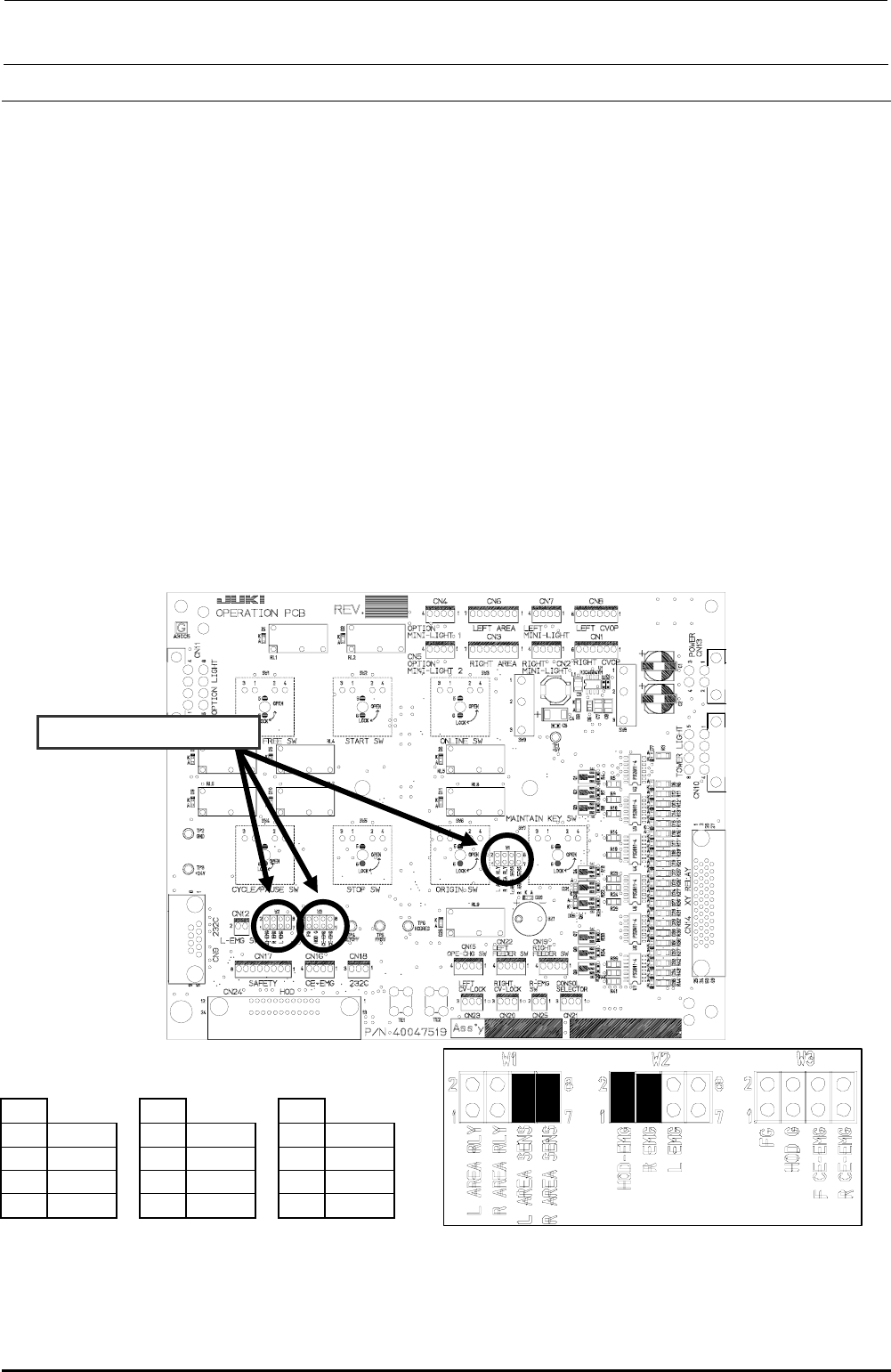
13-9-2. Jumper Switch Settings on the Operation Board Assembly
Check the jumper switch settings on the operation board assembly and the operation board rear
assembly while referring to Figure 13-9-2-1. Additionally, check also the jumper switch settings on
the operation board front assembly (EN) and the operation board rear assembly (EN) while
referring to Figure 13-9-2-2.
c Operation board jumper switch settings
Check W1, W2, and W3.
W1
W2
W3
1-2
Open
1-2
Short
1-2
Open
3-4
Open
3-4
Short
3-4
Open
5-6
Short
5-6
Open
5-6
Open
7-8
Short
7-8
Open
7-8
Open
Mount receptacles at the ■ portions of the straight headers W1, W2, and W3 to make them
short-circuited.
Figure 13-9-2-1 Operation Board Jumper Switch Settings
Rev. 1.00
FX-3R Maintenance Guide
13-50
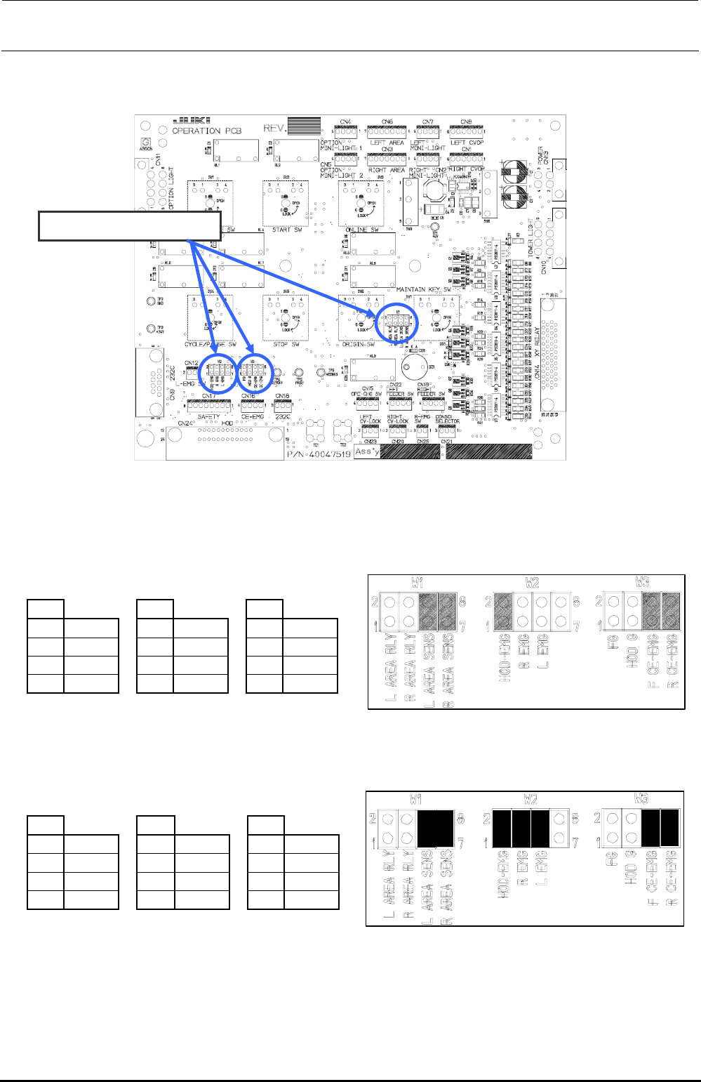
d Operation board (EN) jumper switch settings
Check W1, W2, and W3.
• Jumper switch setting (front)
W1
W2
W3
1-2
Open
1-2
Short
1-2
Open
3-4
Open
3-4
Open
3-4
Open
5-6
Short
5-6
Open
5-6
Short
7-8
Short
7-8
Open
7-8
Short
Mount receptacles at the ■ portions of the straight headers W1, W2, and W3 to make them short-circuited.
• Jumper switch setting (rear)
W1
W2
W3
1-2
Open
1-2
Short
1-2
Open
3-4
Open
3-4
Short
3-4
Open
5-6
Short
5-6
Short
5-6
Short
7-8
Short
7-8
Open
7-8
Short
Mount receptacles at the ■ portions of the straight headers W1, W2, and W3 to make them short-circuited.
Figure 13-9-2-2 Operation board (EN specification) jumper switch settings
Rev. 1.00