fx3r.pdf - 第224页
FX-3R Maintenance Guide 13-55 2) Mounting switches Lenses Green, red, yellow Switch actuator Bezel W ith/without cover +24V LEDs Green, orange Projection s ha ll face leftw ard. <Procedure> (1) ONLINE, ORIGIN, STAR…
FX-3R Maintenance Guide
13-54
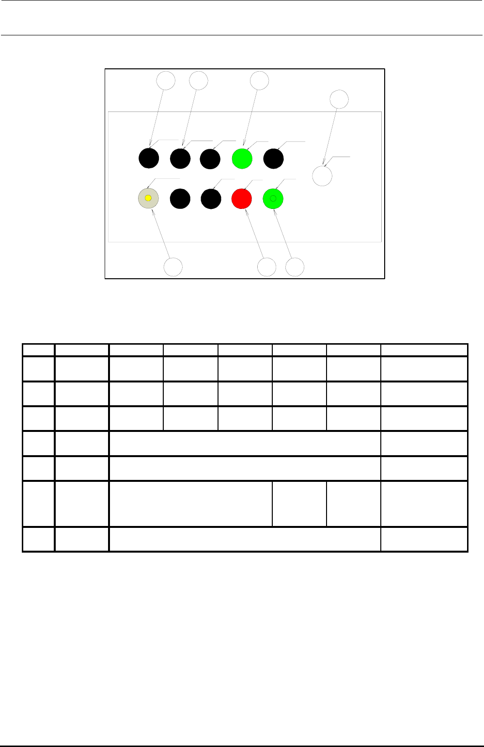
(4) EN rear
LEFT FEEDER
RIGHT FEEDER ONLINE
START SERVO FREE
CONSOLE CHANGE
ORIGIN
STOP
CYCLE
EMERGENCY
SW11 SW14 SW15
SW16
SW17
SW12 SW13
[Option]
Figure 13-9-3-4 Operation Switches (EN Rear)
Table 13-9-3-4 List of Operation Switch Replacement Parts (EN Rear)
HA00553002A
OPTION
(REAR MONITOR)
If the rear motor OP is not
provided, “HX00326000A” is
mounted.
SW17
EMERGENCY 4008956
SW16
CONSOLE
CHENGE
40048036 HA005530010
“HX00326000A” is assembled.
SW15
RIGHT
FEEDER
SW14
LEFT
FEEDER
“HX00326000A” is assembled.
HA00552001B
SW13
CYCLE HA005340010 HA005340020 HA005340070 HA005520030
HA005520030 HA00552001B
SW12
STOP HA005340010 HA005340020 - HA005520030 HA005520010
START HA005340010 HA005340020 -
No.
Switch name Element Actuator LED Bezel Lens Remarks
SW11
Rev. 1.00
FX-3R Maintenance Guide
13-55
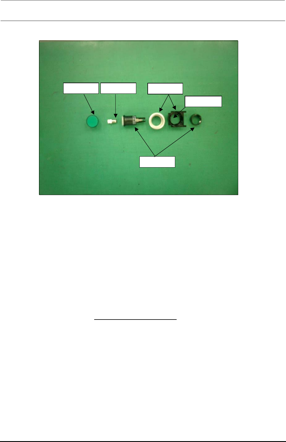
2) Mounting switches
Lenses
Green, red, yellow
Switch actuator
Bezel
With/without cover
+24V LEDs
Green, orange
Projection shall
face leftward.
<Procedure>
(1) ONLINE, ORIGIN, START, STOP, SERVOFREE, CYCLE switches
• Parts used
Lens for flat (HA005520010, HA00552001A, HA00552001B)
LED (HA005340070, HA00534007A)
Bezel (HA005520030, HA00534004A)
Switch actuator (HA005340020)
<Procedure>
c Fit the bezel (black) into the cover panel.
The bezel has a projection to stop rotation.
Attach the bezel so that
the projection faces to the left when viewed from the front.
d Insert the LED into the switch actuator, and fit the actuator over the projection of the bezel
carefully. There is a nut to be used to fix the bezel, so remove it.
e Insert the bezel (silver) from the back of the panel and secure it with the fixing nut.
f Finally, fit the lens for flat into the switch actuator firmly.
∗ References are shown on the following page.
Rev. 1.00
FX-3R Maintenance Guide
13-56
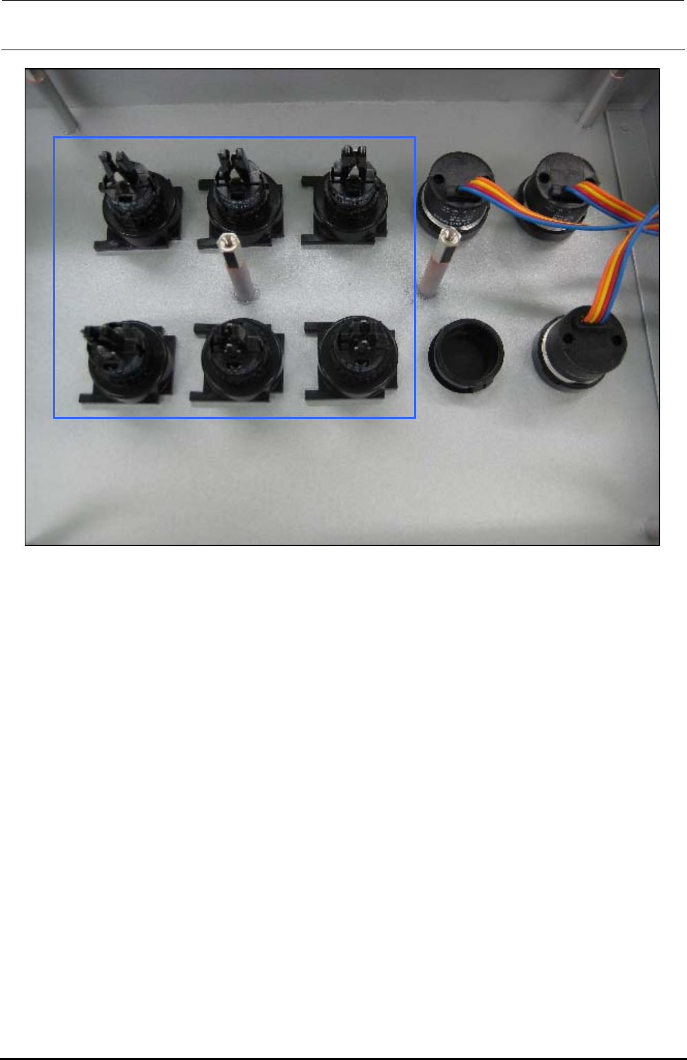
The above Photo shows the back side of the operation panel of the machine with the ST
specifications. When assembling the operation switches (1) and (2), make the convex part of the
switch faced rightward when viewed from the back side of the operation panel as shown in the
Photo.
∗ The Photo shows the back side of the operation panel on the front of the machine with the ST
specifications. Regardless of the front and rear operation panels for the ST and EN
specifications, and bezel shapes (pushbutton type and key type, etc.), always make the convex
part of the switch faced rightward when viewed from the back side of the operation panel.
Rev. 1.00