fx3r.pdf - 第227页
FX-3R Maintenance Guide 13-58 13-10. Replacing the Fuse of the AC Input Unit (Note) Before starting the fuse replacement work, always turn OFF the ma in power of the machine completely. If the fuse of the AC input unit i…
FX-3R Maintenance Guide
13-57
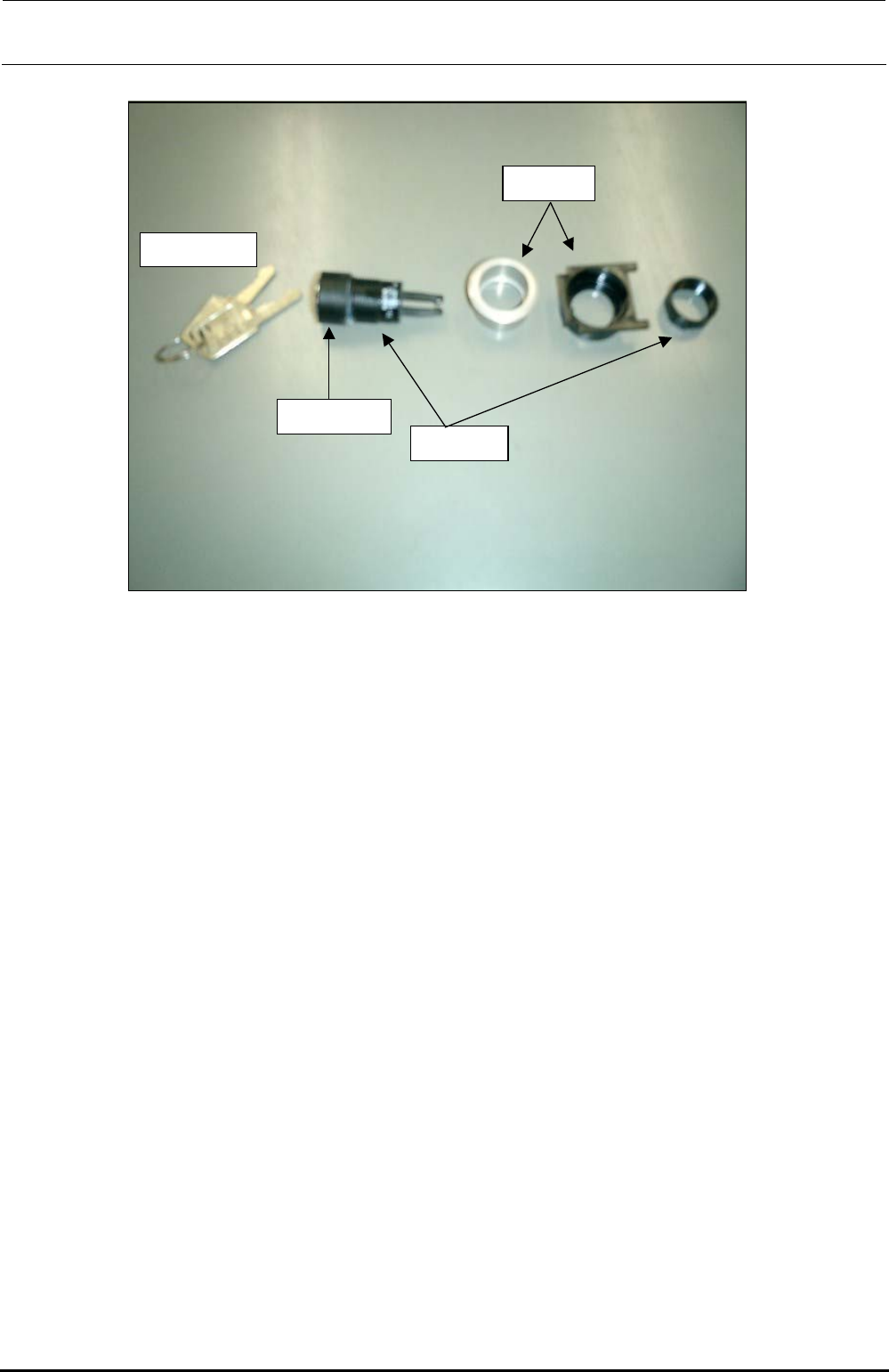
(2) Maintenance key switch
Switch key supplied
with the machine
Bezel for key
switch
Bezel
Key switch
actuator
• Parts used
Key cover (HA00535003A), Key switch actuator (HA005350020), Bezel (HA005520020)
<Assembly procedure>
c Fit the bezel (black) into the cover panel.
d Push the key cover into the key switch actuator until a click is heard.
e Insert the actuator (assembled at 3) into the black bezel, insert the bezel (silver) from the
back of the panel and secure it with the fixing nut.
(3) CONSOLE CHANGE
• Parts used
Use the CONSOLE SW ASM (40048036).
Bezel (white) with a lens: bezel (HA005530010), lens (HA00553002A); to be used for the
CONSOLE CHANGE.
<Assembly procedure>
c Remove the fixing nut of the bezel and fit the bezel. Then tighten the fixing nut.
d Finally, fit the switch element (with a cable) from the back of the panel. Direction of the
switch element is not important. It can be assembled in either direction.
Rev. 1.00
FX-3R Maintenance Guide
13-58
13-10. Replacing the Fuse of the AC Input Unit
(Note) Before starting the fuse replacement work, always turn OFF the main power of
the machine completely.
If the fuse of the AC input unit is blown up, follow the steps below to replace the fuse.
Fuse part No.: HF0013005P0
(Time-lag fuse, 500mA. Three fuses are supplied with the machine as accessory parts.)
<Procedure>
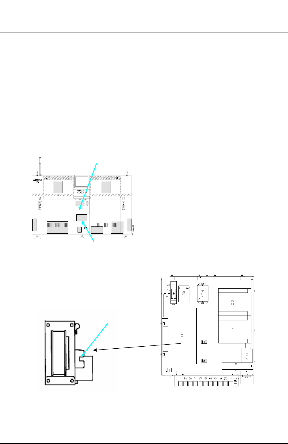
(1) Open the bottom cover on the rear at the center c.
(2) The fuse is mounted at the front left portion of the AC input unit (Figure 13-10-2). Replace
this fuse.
c
AC input unit
Figure 13-10-1 Rear View of Machine
Figure 13-10-3 Top View of AC
Input Unit_L
Figure 13-10-2 Side View of AC
Transformer
Fuse
Rev. 1.00
FX-3R Maintenance Guide
13-59
13-11. Other Boards
13-11-1. XY-RELAY Board (40047558)
[Functions]
This XY-RELAY board relays the signals coming from the limit sensor and emergency stop
switch of each axis to input them to the position board, etc.
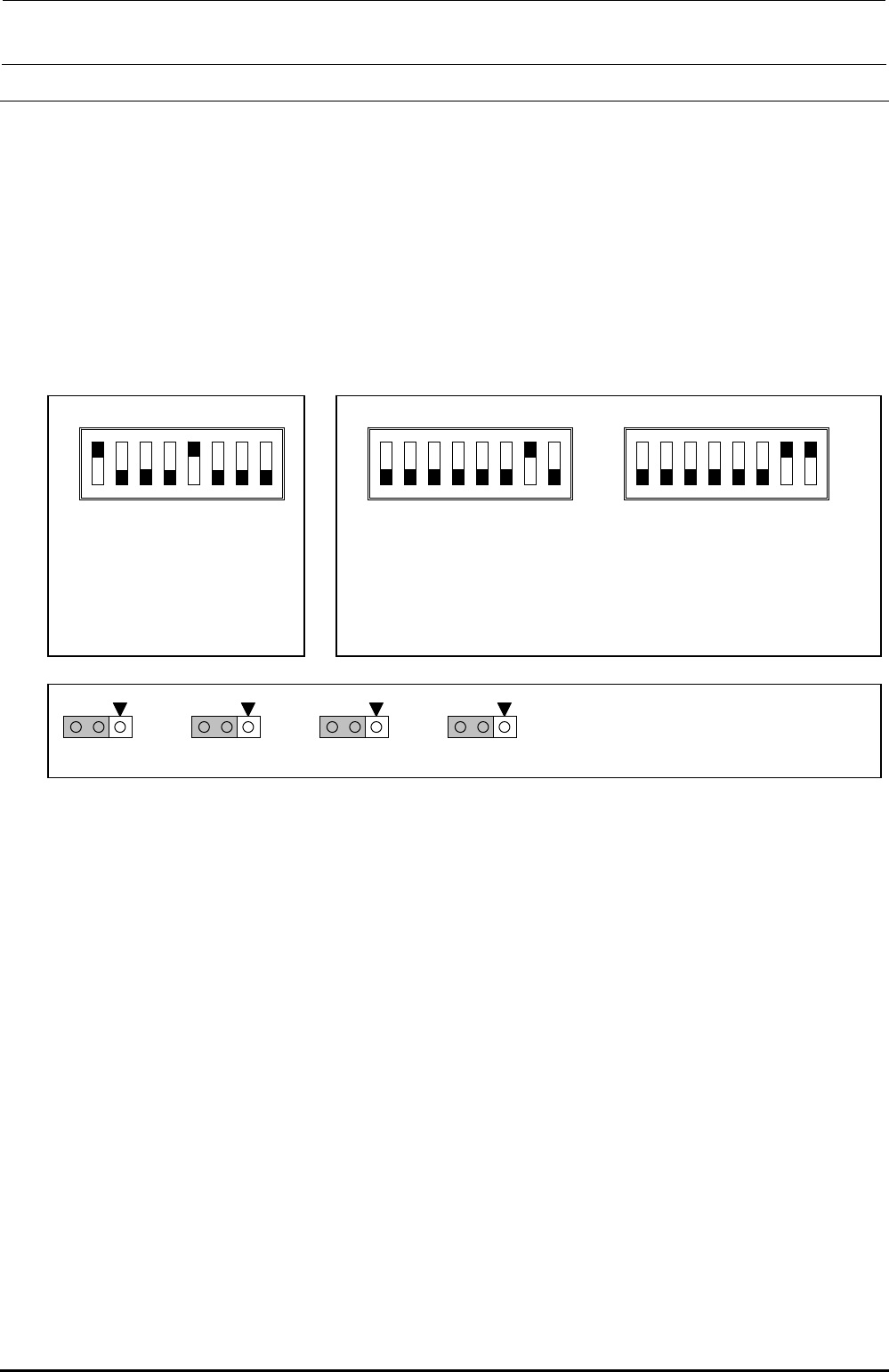
[Jumper switch settings]
portion shows the switch set position and receptacle mounting position.
Rev. 1.00
O
SW3
O
1
2
3
4
5
6
7
8
SW2
O
N
O
N
SW 2 [4..1]: Board function Rev.
SW 2 [8..5]: Board pattern Rev.
This switch has been set properly
before shipment from the factory.
Therefore, do not change this
switch setting. The above Figure
shows just an example.
O
SW3
O
N
[ST specifications: Setting
before shi
p
ment from factor
y]
[EN specifications]
SW3 to 8 are intended to set the power monitor signal valid or invalid, which
is used only for the machines with the EN specifications. Turn ON these
switches for the machines with the EN specifications.
W
5
1
3
W
6
1
3
W
7
1
3
W
8
1
3
A
ll of other W are opened.
These jumper switches have been set properly
before shipping the board. Therefore, do not change
these jumper switches.
1
2
3
4
5
6
1
2
3
4
5
6
7
8
[Adjustment items after replacement]
There are no particular adjustment items.