fx3r.pdf - 第230页
FX-3R Maintenance Guide 13-61 Rev . 1.00 13-11-2. FEEDER Board (40047560) [Functions] One board is arranged for each of the left and right stations, t wo boards in total. c ATC open/close (WRITE) and its check sensor d F…

FX-3R Maintenance Guide
13-60
Rev. 1.00
[Meaning of LED] Part No. 40047558
No. Color Meaning Status
LD1 Orange +3.3V power supply Normal: Lit
LD2 Orange
+3.3V power supply for Ether Slave
Normal: Lit
LD3 Orange +5V power supply Normal: Lit
LD4 Green YL (LF)_Phase A Not used: (Linear scale A-phase signal H/L: Lit/Off)
LD5 Green YL (LF)_Phase B Not used: (Linear scale B-phase signal H/L: Lit/Off)
LD6 Orange YL (LF)_Origin sensor Not used: (Origin sensor detected.: Lit)
LD7 Green YR (LF)_Phase A Not used: (Linear scale A-phase signal H/L: Lit/Off)
LD8 Green YR (LF)_Phase B Not used: (Linear scale B-phase signal H/L: Lit/Off)
LD9 Orange YR (LF)_Origin sensor Not used: (Origin sensor detected.: Lit)
LD10 Green YL (LR)_Phase A Not used: (Linear scale A-phase signal H/L: Lit/Off)
LD11 Green YL (LR)_Phase B Not used: (Linear scale B-phase signal H/L: Lit/Off)
LD12 Orange YL (LR)_Origin sensor Not used: (Origin sensor detected.: Lit)
LD13 Green YR (LR)_Phase A Not used: (Linear scale A-phase signal H/L: Lit/Off)
LD14 Green YR (LR)_Phase B Not used: (Linear scale B-phase signal H/L: Lit/Off)
LD15 Orange YR (LR)_Origin sensor Not used: (Origin sensor detected.: Lit)
LD16 Green YL (RF)_Phase A Not used: (Linear scale A-phase signal H/L: Lit/Off)
LD17 Green YL (RF)_Phase B Not used: (Linear scale B-phase signal H/L: Lit/Off)
LD18 Orange YL (RF)_Origin sensor Not used: (Origin sensor detected.: Lit)
LD19 Green YR (RF)_Phase A Not used: (Linear scale A-phase signal H/L: Lit/Off)
LD20 Green YR (RF)_Phase B Not used: (Linear scale B-phase signal H/L: Lit/Off)
LD21 Orange YR (RF)_Origin sensor Not used: (Origin sensor detected.: Lit)
LD22 Green YL (RR)_Phase A Not used: (Linear scale A-phase signal H/L: Lit/Off)
LD23 Green YL (RR)_Phase B Not used: (Linear scale B-phase signal H/L: Lit/Off)
LD24 Orange YL (RR)_Origin sensor Not used: (Origin sensor detected.: Lit)
LD25 Green YR (RR)_Phase A Not used: (Linear scale A-phase signal H/L: Lit/Off)
LD26 Green YR (RR)_Phase B Not used: (Linear scale B-phase signal H/L: Lit/Off)
LD27 Orange YR (RR)_Origin sensor Not used: (Origin sensor detected.: Lit)
LD28 Red FPGA configuration for Operation I/F Configuration completion: Lit
LD29 Red Console change-over Front valid: Lit., Rear valid: Off
LD30 Yellow
Not used
⎯
LD31 Yellow
Not used
⎯
LD32 Yellow
Not used
⎯
LD33 Yellow
Not used
⎯
LD34 Red FPGA configuration for Ether communication
Configuration completion: Lit
LD35 Blue Not used
⎯
LD36 Blue AreaEMG
Area sensor detection: Off
(However, when SW3_6 = OFF, the LED is always lit.)
LD37 Blue Axis Lim EMG
Axis Lim sensor detection: Off
(However, when SW3_7 = OFF, the LED is always lit.)
LD38 Blue PowerMonEMG (EN)
PowerMon detection: Off
(However, when SW3_8 = OFF, the LED is always lit.)
FX-3R Maintenance Guide
13-61
Rev. 1.00
13-11-2. FEEDER Board (40047560)
[Functions]
One board is arranged for each of the left and right stations, two boards in total.
c ATC open/close (WRITE) and its check sensor
d Feeder rise sensor, feeder detection sensor
e Bank up sensor is detected.
f CAL block LED is lit and vacuum is turned ON.
g Vacuum calibration sensor
h Feeder knock pin is driven.
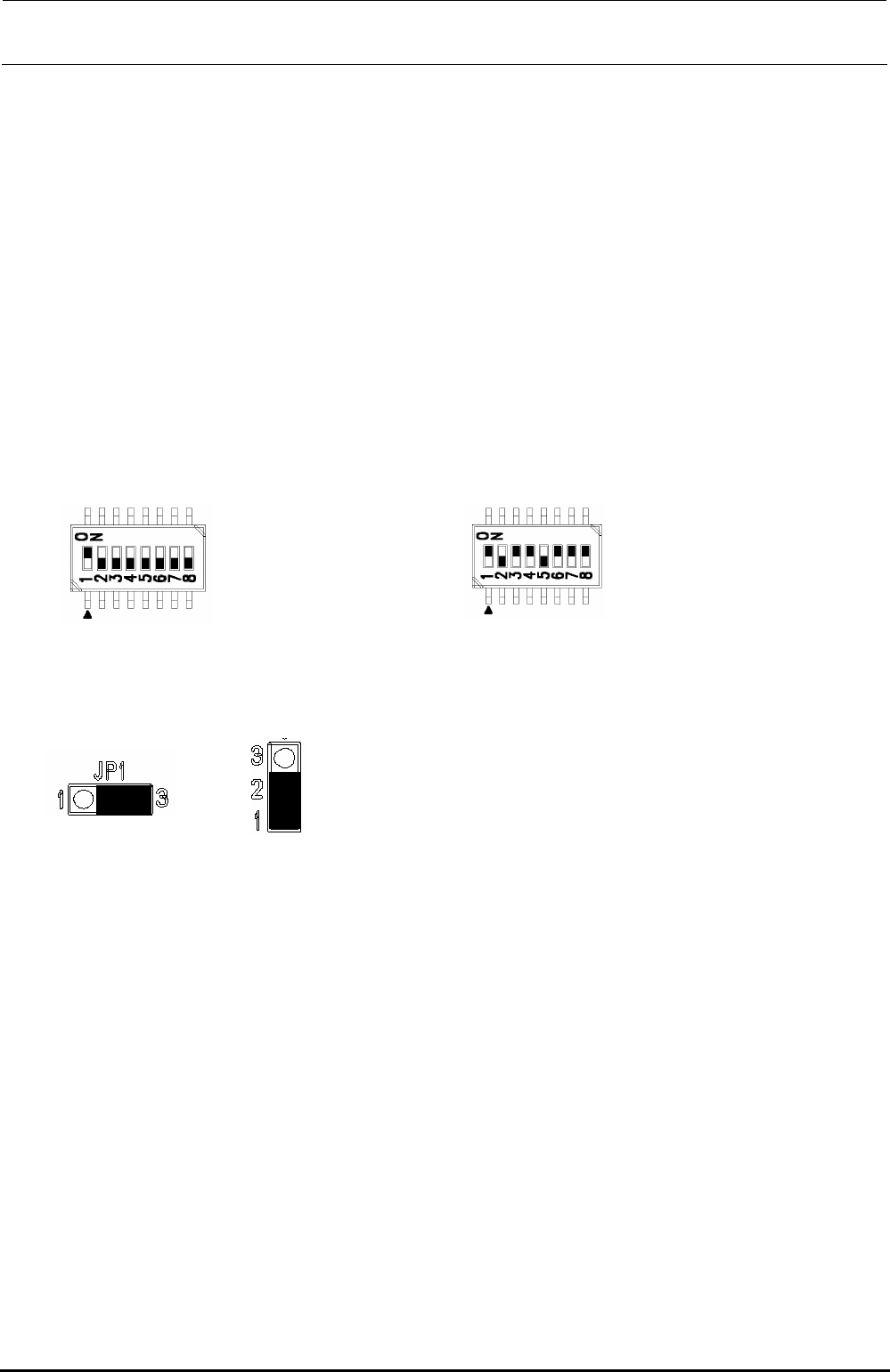
[Jumper switch settings]
portion shows the switch set position and receptacle mounting position.
DSW1 DSW2
[Adjustment items after replacement]
After that, follow the steps below to update the FLASH memory.
c Select [Options] and [Change User Group], and then select [Serviceman].
d Select [Maintenance] and [MS Parameter Setup].
e Select [Upgrade] and [Feeder].
f Clicking [Exec.] will start the upgrading process.
Jumper JP1 Jumper JP2 to 11
SW 2 [4..1]: Board function Rev.
SW 2 [8..5]: Board pattern Rev.
This switch has been set properly before shipment from
the factory. Therefore, do not change this switch setting.
The above Figure shows just an example.
No. 1: ON
No. 2 to 8: OFF
FX-3R Maintenance Guide
13-62
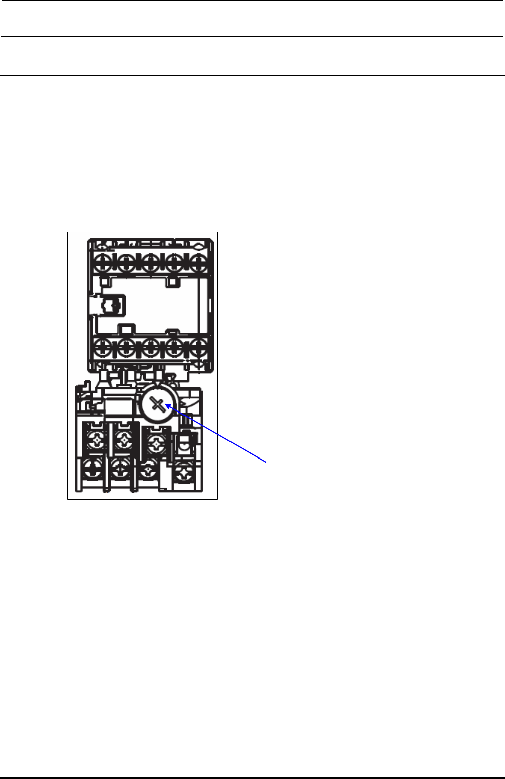
13-12. Adjusting the Dial of the Vacuum Pump Electromagnetic Switch
(Thermal Protector)
[Functions]
The temperature and current are monitored to prevent the over-current from flowing to the
vacuum pump caused by the electromagnetic switch (thermal protector) in the noise filter
assembly.
[Settings]
Setting current dial adjustment value: 4.4A
Dial for adjustment of setting current
Figure 13-12-1 Dial for Adjustment of Setting Current of Electromagnetic Switch
(Thermal Protector)
Rev. 1.00