fx3r.pdf - 第231页
FX-3R Maintenance Guide 13-62 13-12. Adjusting the Dial of the Vac uum Pump Electromagnetic Switch (Thermal Protector) [Functions] The temperature and current are monitored to prev ent the over-current from flowing to th…
FX-3R Maintenance Guide
13-61
Rev. 1.00
13-11-2. FEEDER Board (40047560)
[Functions]
One board is arranged for each of the left and right stations, two boards in total.
c ATC open/close (WRITE) and its check sensor
d Feeder rise sensor, feeder detection sensor
e Bank up sensor is detected.
f CAL block LED is lit and vacuum is turned ON.
g Vacuum calibration sensor
h Feeder knock pin is driven.
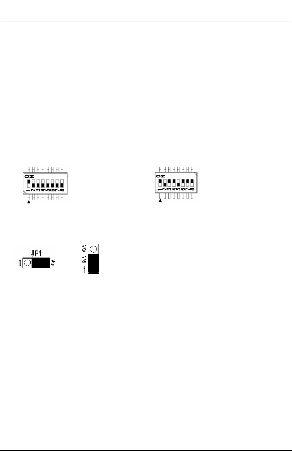
[Jumper switch settings]
portion shows the switch set position and receptacle mounting position.
DSW1 DSW2
[Adjustment items after replacement]
After that, follow the steps below to update the FLASH memory.
c Select [Options] and [Change User Group], and then select [Serviceman].
d Select [Maintenance] and [MS Parameter Setup].
e Select [Upgrade] and [Feeder].
f Clicking [Exec.] will start the upgrading process.
Jumper JP1 Jumper JP2 to 11
SW 2 [4..1]: Board function Rev.
SW 2 [8..5]: Board pattern Rev.
This switch has been set properly before shipment from
the factory. Therefore, do not change this switch setting.
The above Figure shows just an example.
No. 1: ON
No. 2 to 8: OFF
FX-3R Maintenance Guide
13-62
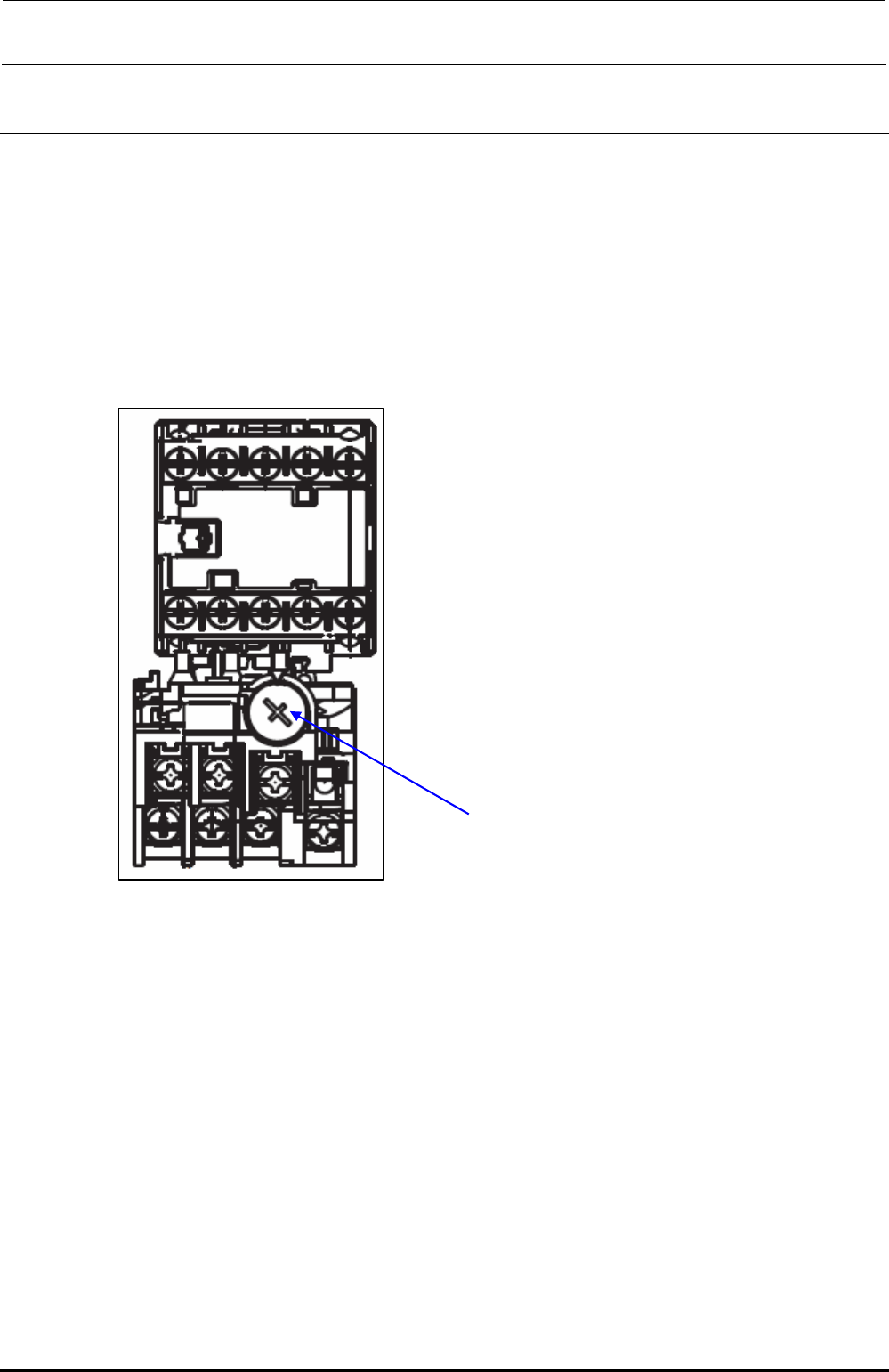
13-12. Adjusting the Dial of the Vacuum Pump Electromagnetic Switch
(Thermal Protector)
[Functions]
The temperature and current are monitored to prevent the over-current from flowing to the
vacuum pump caused by the electromagnetic switch (thermal protector) in the noise filter
assembly.
[Settings]
Setting current dial adjustment value: 4.4A
Dial for adjustment of setting current
Figure 13-12-1 Dial for Adjustment of Setting Current of Electromagnetic Switch
(Thermal Protector)
Rev. 1.00
FX-3R Maintenance Guide
14-1
DANGER
To prevent any trouble caused by accidental machine start, always
shut-down the power before starting the maintenance and
adjustment work.
[14] FEEDER POSITION INDICATOR (FPI)
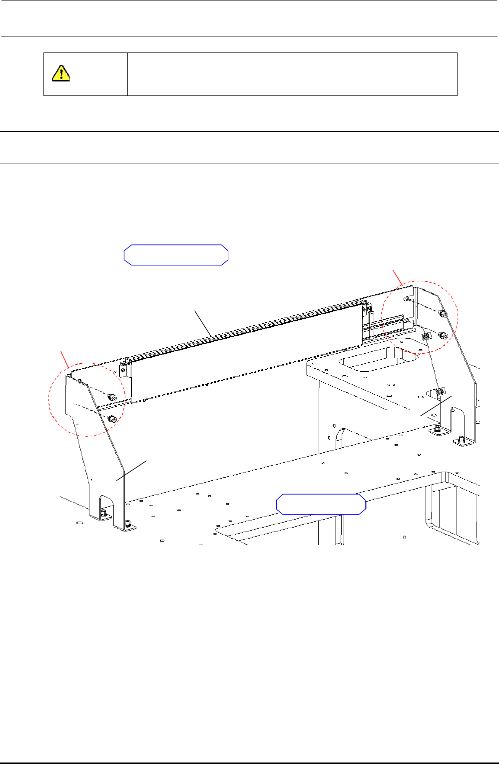
14-1. Detaching the FPI (Front) from the Machine Main Unit
As shown in the Figure below, the FPI bracket assembly is secured to the FPI bracket L/R with the
SEMS cap bolts (M6 × 12), which has been fixed to the base frame.
Remove four bolts to detach the FPI bracket assembly.
FPI BRACKET R
FPI BRACKET L
FPI BRACKET ASM
SEMS cap bolt (M6 × 12)
2 pcs.
Outside of machine
SEMS cap bolt (M6 × 12)
2 pcs.
Inside of machine
Figure 14-1-1 Detaching the FPI
Rev. 1.00