fx3r.pdf - 第246页
FX-3R Maintenance Guide 15-12 Rev. 1.00 15-4. Replacing the Fixed Cutter Blade (Upper Blade) of the Tape Cutter ∗ Replace the fixed cutter blade after the cutter main unit has been detached from the FX -3 main unit. 1) D…
FX-3R Maintenance Guide
15-11
Rev. 1.00
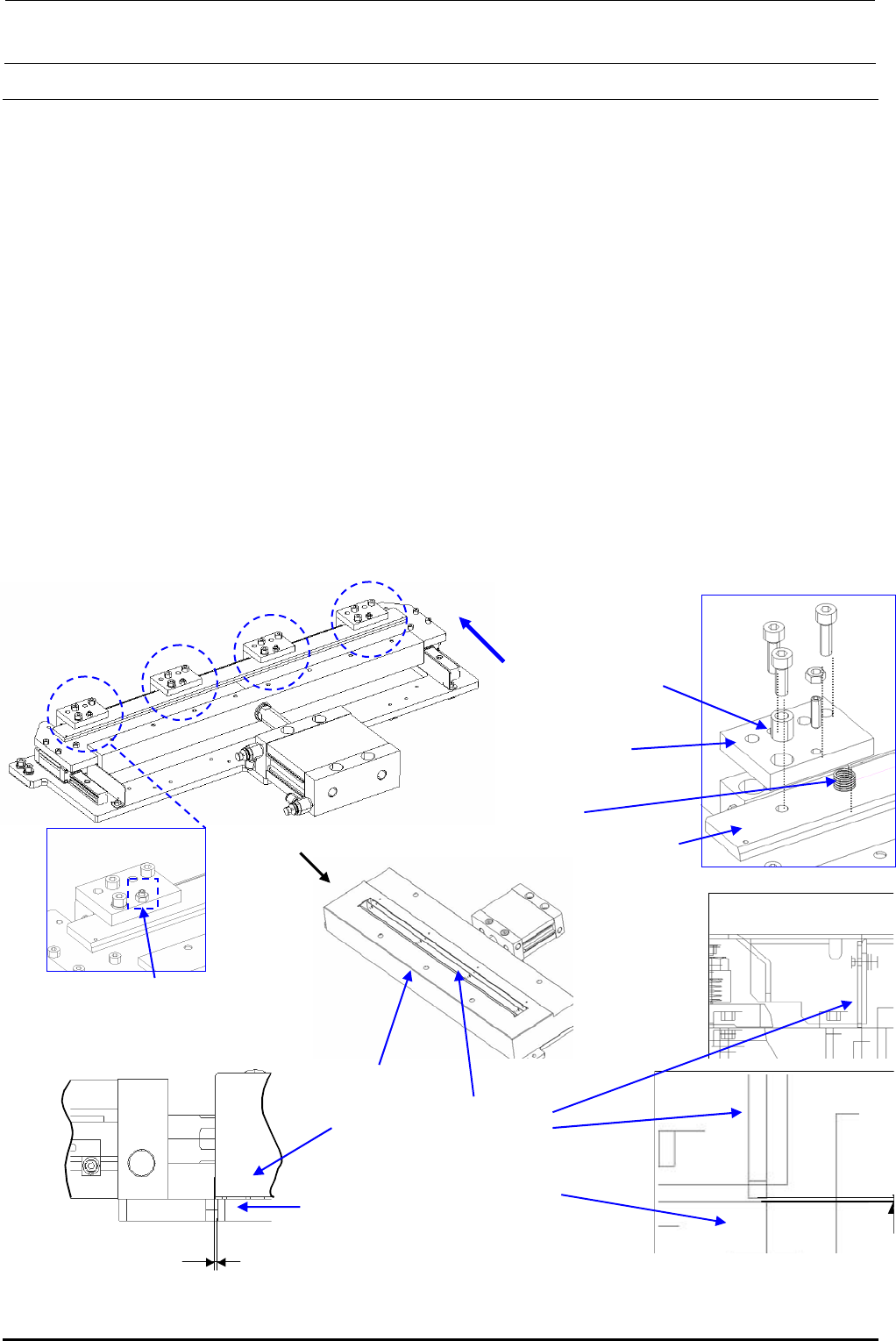
• SM6085002TN: Hexagon socket head cap bolt
• WS0820002KN: Spring washer M8
Movable cutter blade
Fixed cutter blade
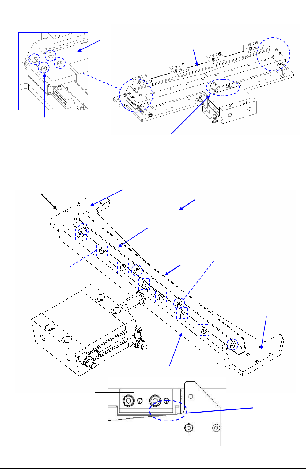
Figure 15-3-2 Detachment of Movable Cutter Blade
Figure 15-3-3 Replacement of Movable Cutter Blade
SM6041402TN
Hexagon socket head
cap bolt
M4 × 0.7, L = 14
40084688
Bottom blade R
40084687
Bottom blade L
40084689
Joint bar
40084692
Upper tape guard
SM6040802TN
Hexagon socket head
cap bolt
M4 × 0.7, L = 8
SM6051602TN
Hexagon socket head
cap bolt
Push all
the way
Push all
the way
Shift the components
to assemble them.
40084685
Upper blade support base
Clearance
check location
FX-3R Maintenance Guide
15-12
Rev. 1.00
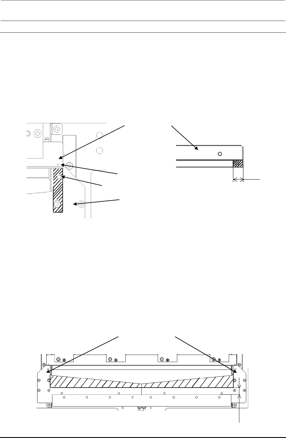
15-4. Replacing the Fixed Cutter Blade (Upper Blade) of the Tape Cutter
∗ Replace the fixed cutter blade after the cutter main unit has been detached from the FX-3 main
unit.
1) Detach the cutter cover and cylinder cover. (See 15-3.)
2) Put the movable cutter blade in the closed status. Remove the slitting set screws for
adjustment of the pushing pressure and fixed cutter blade mounting screws. (Pay special
attention so that any spring or bushing is not lost.)
3) Detach the upper blade support to replace the fixed cutter blade.
4) Reassemble the components in the reverse order of disassembly.
5) Adjust the pushing pressure of the fixed cutter blade. (See page 1 of M11_TAPE_CUTTER in
the QA table.)
6) After the fixed cutter blade has been replaced, apply the grease (Alvania grease). For details
about grease application locations and procedures, see section 15-5, Grease up.
7) After the fixed cutter blade has been replaced, assemble the cutter cover. Make the
adjustment so that the cover projects 1 mm toward you from the end face of the cutter base.
8) After the cover has been assembled, readjust the clearance between the guide plate (Teflon
sheet) and movable cutter blade to 0.1 to 0.15 mm.
Figure 15-4-1 Replacement of Fixed Cutter Blade
Close the movable
cutter blade.
40084684
Upper blade support
0.1~0.15
40084683
Guide plate
Bottom blade
1
View of A
A
40084682
Cutter cover
Cutter base
E6109700000
Upper blade
bushing
E6110700000
Upper blade
SP-A
SM8041402TP: Set screw, M4 × 0.7, L = 14
NM6040001SC: Hexagon nut, M4 × 0.7
40084686
Upper blade
0.1 to 0.15
FX-3R Maintenance Guide
15-13
15-5. Grease up
Use Alvania grease for all grease up locations.
1) Apply the grease to areas of 10 mm from both ends of the polished surface on the bottom of
the upper blade (See the figure below).
2) After the upper blade has been assembled, apply the grease to areas of 10 mm from both
ends of the bottom cutter blades L and R (see the figure below) and fill the holes A and B with
the grease.
3) Open and close the cutter blade several times and wipe off the grease sticking to a portion
other than the sliding part.
10
40084686
Upper blade
Rear
A
B
40084687
40084688
Bottom blades L and R
Figure 15-5-1 Grease Up Locations (1)
4) Adjust the pushing pressure of the fixed blade. (See page 1 of M11_TAPE_CUTTER in the
QA table.)
5) Apply the grease to the hatched portion at the center of the bottom blade (See the figure
below). After the grease has been applied, wipe off the grease so that the thin oil coat is
seen.
∗ Open and close the cutter several times. If the oil coat lines are seen, the amount of the
applied grease is excessive. Conversely, if no oil coat lines are seen, the amount of the
applied grease is insufficient.
6) Wipe off the grease sticking to a portion other than the sliding part.
Figure 15-5-2 Grease Up Locations (2)
40084687
40084688
ボトムブレード L、R
25
40084687
40084688
Bottom blades L and R
Rev. 1.00