fx3r.pdf - 第35页
FX-3R Maintenance Guide 3-3 3-2. Replacing the Filter Before replacing the filter, always shut-down the main compressed air. <Replacing the head filter> 1) Remove the cap bolts c ( × 2) and cap bolts d ( × 2) to de…
FX-3R Maintenance Guide
3-2
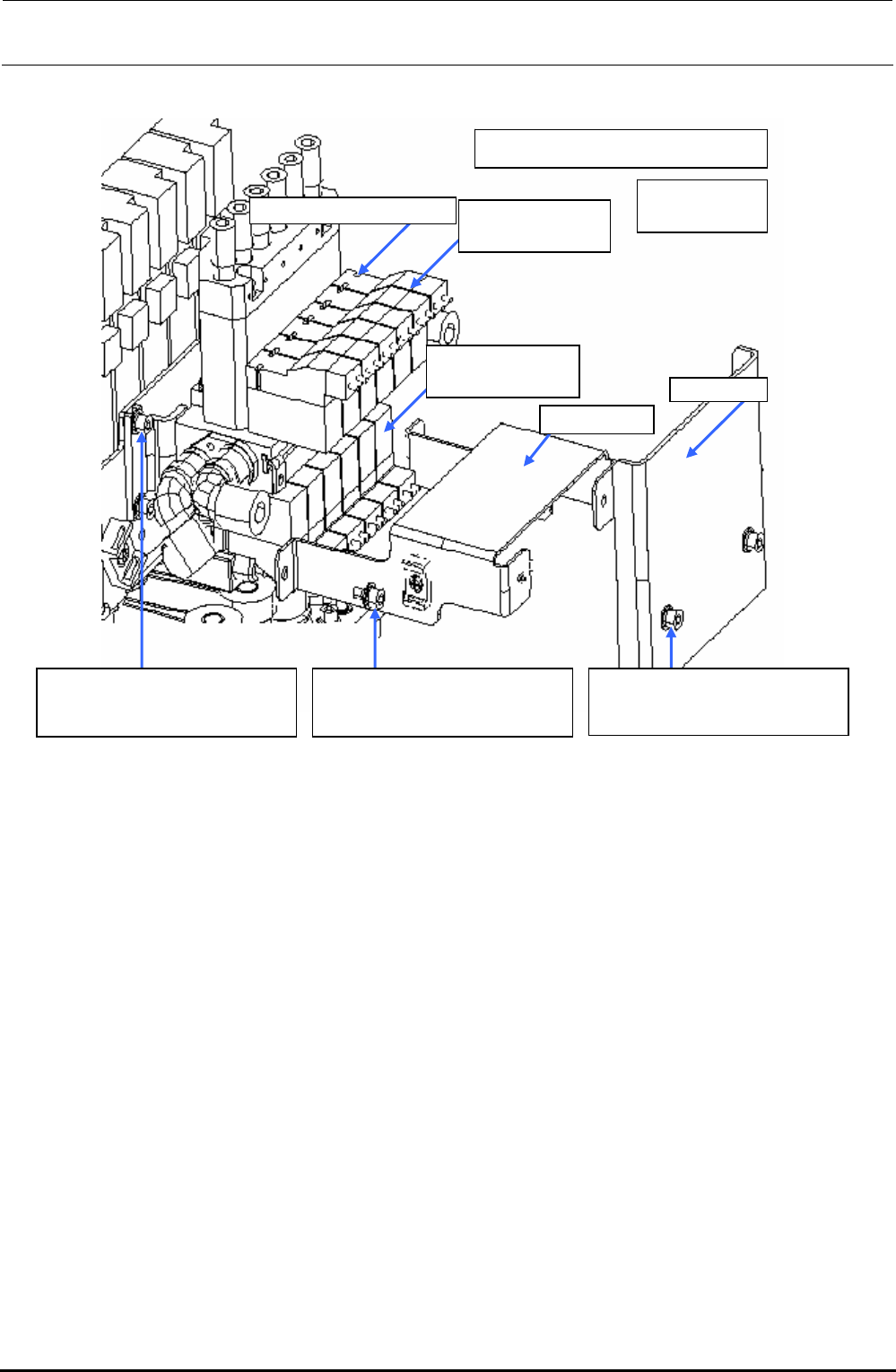
Tightening torque: 0.15±0.02 N⋅m
SV cover
Cable guide
40046835
Solenoid valve
40068170
Solenoid valve B
40068169
Solenoid valve V
Round head screw f (
×
2)
c SL6030692TN
SEMS cap bolt with washer
M3×6
d SL6030692TN
SEMS cap bolt with washer
M3×6
e SL6030692TN
SEMS cap bolt with washer
M3×6
Figure 3-1-1 Replacing the Solenoid Valves
Rev. 1.00
FX-3R Maintenance Guide
3-3
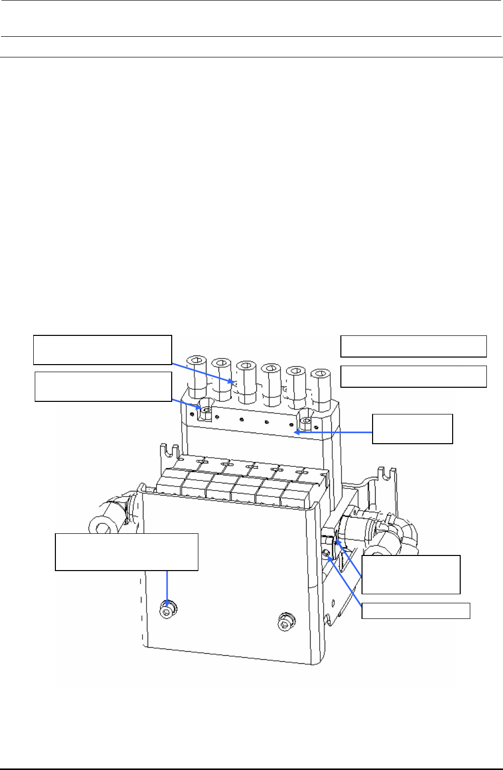
3-2. Replacing the Filter
Before replacing the filter, always shut-down the main compressed air.
<Replacing the head filter>
1) Remove the cap bolts c (×2) and cap bolts d (×2) to detach the filter box U.
(O-ring is mounted under the filter box U. Carefully handle this O-ring so that it is not lost.)
2) Take out the filter and replace it with a new one.
3) Reassemble the parts and components in the reverse order of disassembly.
4) After the filter has been replaced, check the filter through the head vacuum and the blow
ON/OFF of the manual control.
<Replacing the filter for release to atmosphere>
1) Remove the SEMS cap bolts e (×2) to detach the SV cover.
2) Loosen the SEMS cap bolts f (×2) to detach the filter for release to atmosphere.
(You can detach the filter only by loosening the SEMS cap bolts.)
3) Reassemble the parts and components in the reverse order of disassembly.
∗ SEMS cap bolts f (2 pcs.) are accessory parts supplied with the solenoid valve.
c Tightening torque: 0.9N
⋅
m
d SM6034002TN
SEMS cap bolt M3×40
d Tightening torque: 0.6N
⋅
m
E3052729000
Head filter
e SL6030692TN
SEMS cap bolt with washer
M3×6
40068171
Filter for release to
atmosphere
SEMS cap bolt f (
×
2)
c SM6031602TN
SEMS cap bolt M3×16
Figure 3-2-1 Replacing the Head Filter
Rev. 1.00
FX-3R Maintenance Guide
3-4
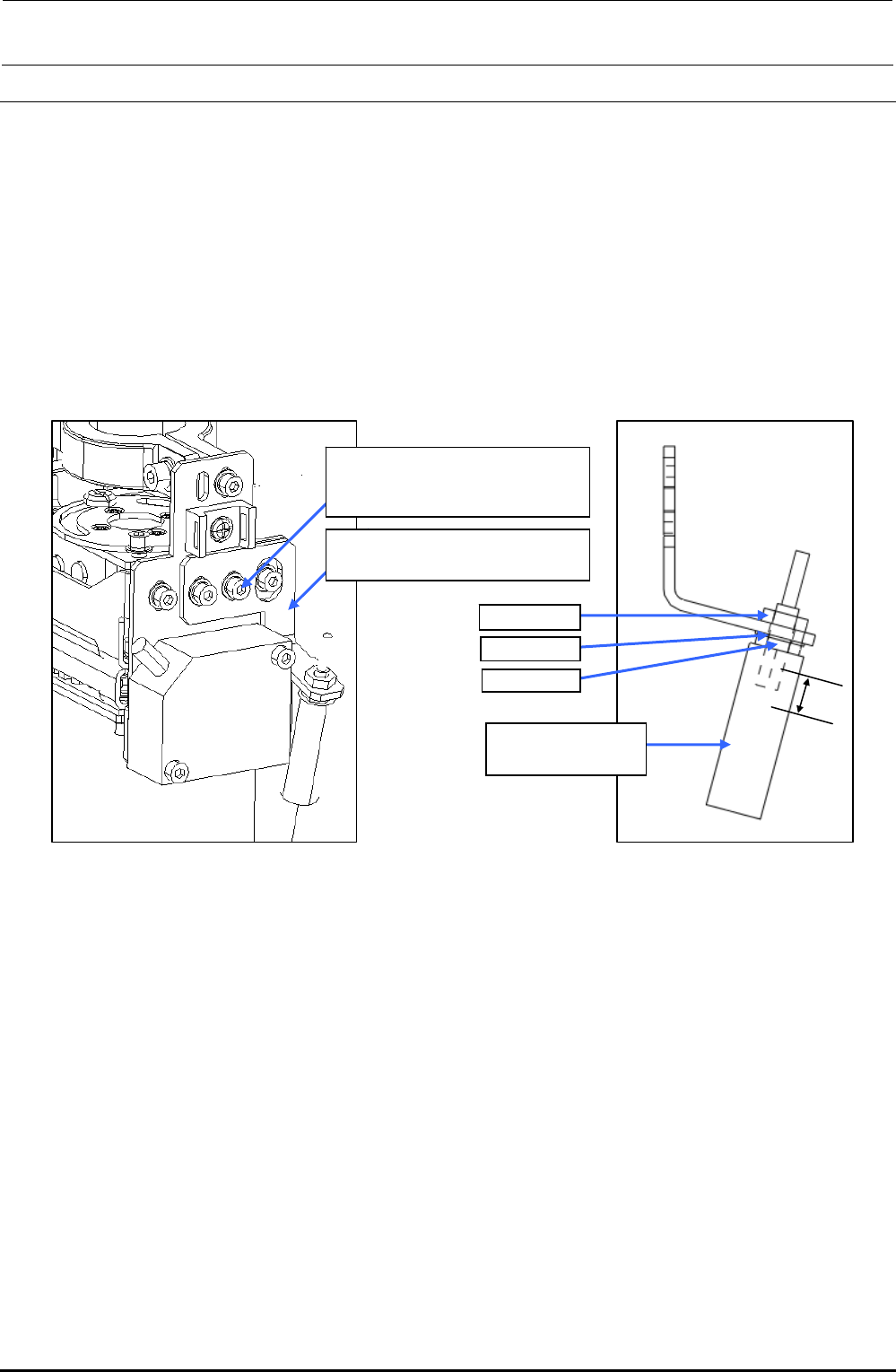
3-3. Replacing the Bad Mark Sensor
3-3-1. Sensor Assembly
1) Remove the SEMS cap bolts c (×2) to detach the BMR lens bracket A (B). (The following
Figure shows the BM lens bracket A (for RR head).)
2) Remove the nut d and washer e to detach the lens f.
3) Reassemble the parts and components in the reverse order of disassembly.
In the same manner as described above, remove the BMR lens bracket B (for LR head).
∗ Nuts d (2 pcs.) and washer e are accessory parts supplied with the fiber unit.
c SL6030692TN
SEMS cap bolt with washer
M3×6
RR-head: BMR lens bracket A
LR-head: BMR lens bracket B
Nut d
Washer e
Nut d
f E9638729000
Fiber lens
7mm
Figure 3-3-1-1 Replacing the BMR Lens
Rev. 1.00