fx3r.pdf - 第38页
FX-3R Maintenance Guide 3-6 3-3-4. Assembling the Fiber Unit to the Amplifier 1) Open the case cover and flip down the one-touch lock lever. 2) Make the projection faced toward the side where there is no LED and insert t…
FX-3R Maintenance Guide
3-5
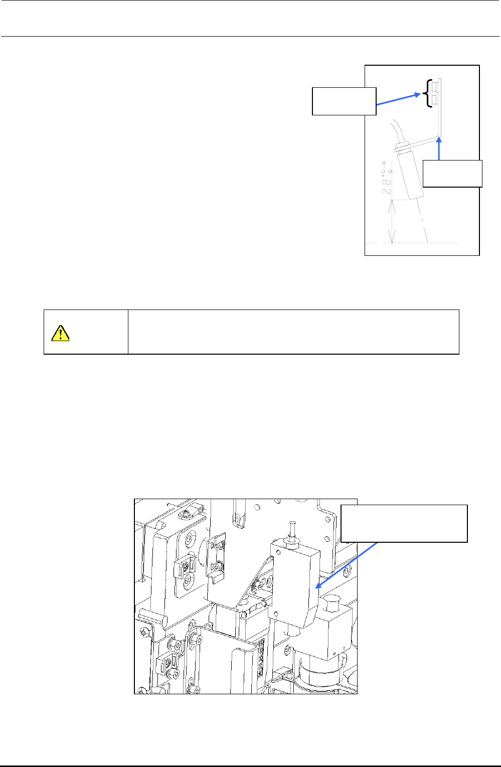
3-3-2. Adjusting the Sensor Height
CALブロック
上面
SEMS cap
bolt M3×6
BMR lens
bracket
CAL block
top surface
Move the bad mark sensor to a point above the calibration
block. Loosen the SEMS cap bolts at two places and move
the BMR lens bracket so that the distance between the
surface of the bad mark sensor and the top surface of the
calibration block becomes 28
0
+05
mm.
After the sensor height has been adjusted, secure the bad
mark sensor with SEMS cap bolts.
After the bad mark sensor has been mounted properly,
input the bad mark sensor offset of the MS parameters.
(For details about how to input MS parameters, see “MS
Parameters”.)
Figure 3-2-2-1 Adjusting the
Lens Height
CAUTION
To prevent any personal injury, do not put your hand inside the
machine or your face or head close to the machine during operation
of the touch panel and/or HOD.
3-3-3. Amplifier
1) Detach the amplifier while keeping the amplifier pushed downward. (The following Figure
shows the RR head.)
2) Reassemble the parts and components in the reverse order of disassembly. In the same
manner as described above, detach the amplifier from the LR head.
40047981
Bad mark fiber amplifier
assembly
Figure 3-3-3 Assembling the Amplifier
Rev. 1.00
FX-3R Maintenance Guide
3-6
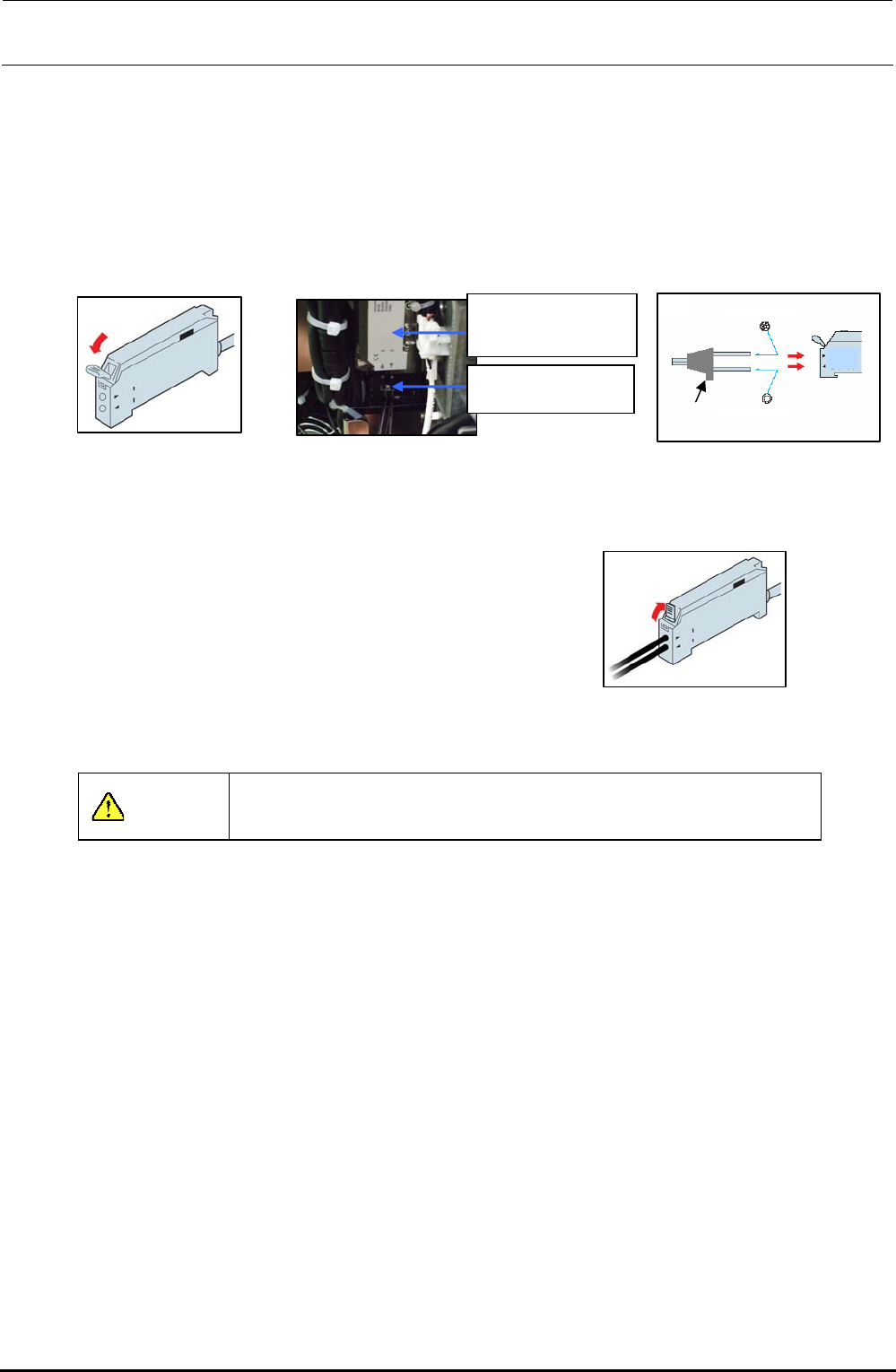
3-3-4. Assembling the Fiber Unit to the Amplifier
1) Open the case cover and flip down the one-touch lock lever.
2) Make the projection faced toward the side where there is no LED and insert the fiber into the
amplifier approx. 13 mm.
After the fiber has been inserted, flip up the lock lever and check that the fiber is not
disconnected. After that, close the case cover.
2)
Projection
Multi-core fibe
r
Single-core fiber
Light receiving side
Light emitting side
Figure 3-3-4-3
Inserting the Fiber
1
)
Figure 3-3-4-1 Amplifier
40047981
Bad mark fiber
amplifier assembly
HD001310030
Fiber unit
Figure 3-3-4-2
Assembling the Amplifier
3) Flip up the one-touch lock lever. Check that the fiber
is not disconnected.
3
)
Figure 3-3-4-4 Fixing the Fiber
CAUTION
Always carry out the wiring work with the power turned OFF.
Rev. 1.00
FX-3R Maintenance Guide
3-7
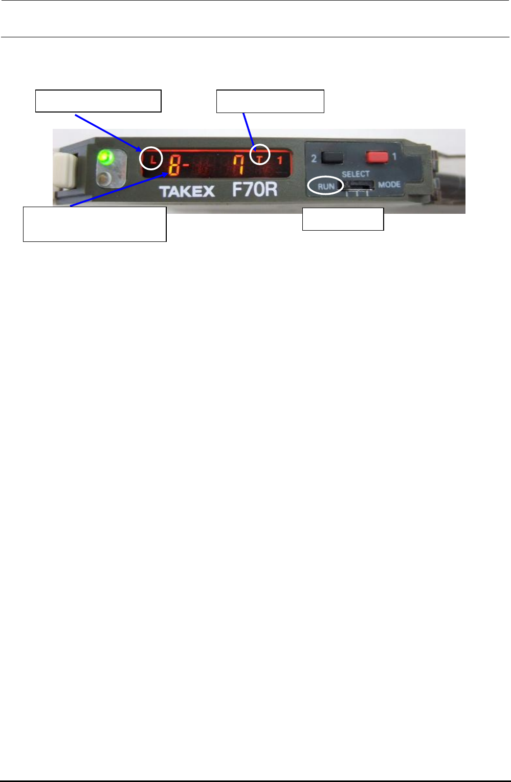
3-3-5. Amplifier Setting
Use as it is the amplifier in the factory-settings.
Turn on the power supply to make sure that the status shown in the following figure is provided.
Rev. 1.00
<LED status>
L = Light ON operation
Mode switch
Electronic volume position
8 = Maximum sensibility
T = Teaching mode
Figure 3-3-5-1 Bad Mark Sensor Indication
The orange and green LEDs come on simultaneously. → Stable operation status at ON
Only the orange LED comes on. → Unstable operation status at ON
The orange and green LEDs go out simultaneously. → Unstable operation status at OFF
Only the green LED comes on. → Stable operation status at OFF