fx3r.pdf - 第49页
FX-3R Maintenance Guide 4-5 ∗ Adjusting the polarizing filter 1) Put a white ceramic board on the calibration block and move the camera above the board. 2) Loosen the setscrew. Turn the light filter U support and secure …
FX-3R Maintenance Guide
4-4
4-4. Replacing the Lens Filter
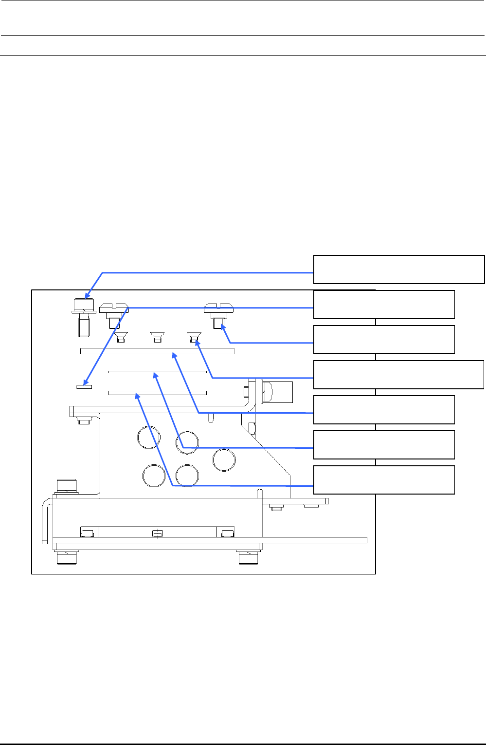
1) Detach the light assembly from the XM base using the procedure described in "Replacing the
OCC Assembly".
2) Remove the SEMS cap bolt c (×1), collar d (×1) and shoulder screws e (×2) to detach the
light filter U support, lens filter and guide plate.
3) Remove the countersunk-head screws f (×4) to detach the lens filter。
4) Reassemble the components in the reverse order of disassembly.
5) After the filter has been replaced, it is necessary to adjust the polarizing filter and OCC light.
(See 4-8, "List of Readjustment Items after Replacement".)
c SL6030892TN
SEMS cap bolt with washer M3×8
d 40015847
OCC collar
e E1038871000
Platen lock cam screw
f SM1030501SC
Countersunk-head screw M3×5
40013949
Light filter U support
40043896
Lens filter
40013948
Guide plate
Figure 4-4-1 Replacing the Lens Filter
Rev. 1.00
FX-3R Maintenance Guide
4-5
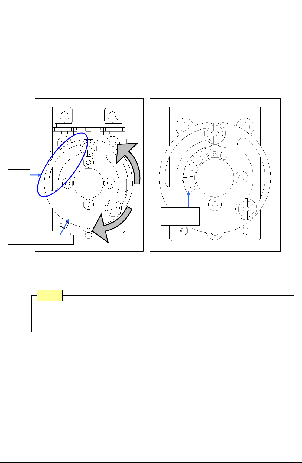
∗ Adjusting the polarizing filter
1) Put a white ceramic board on the calibration block and move the camera above the board.
2) Loosen the setscrew. Turn the light filter U support and secure it when the screen is at the
brightest level.
3) In the brightest status, re-stick the OCC light label as shown in the figure below.
Rev. 1.00
2) 3)
Slit
40015962
OCC label
Light filter U support
Figure 4-4-2 Filter Adjusting Position and Sticking the Light Label
After adjustment, if the slit position of the light filter U support is displaced 90 degrees,
rotate the lens filter 90 degrees and readjust the polarizing filter so that the position of
the slit is the same as the orientation on Figure 4-2-2.
Note
FX-3R Maintenance Guide
4-6
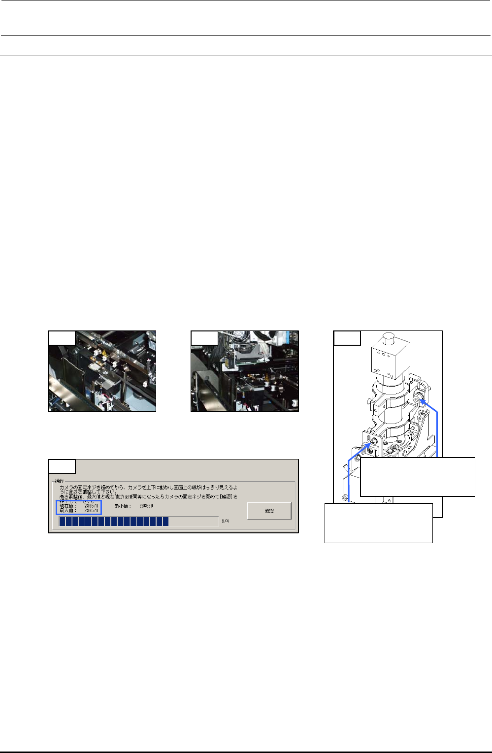
4-5. Adjusting the Focus
<Procedure>
1) Mount the OCC focus adjustment jig on the calibration block.
2) Move the OCC camera to a position above the OCC focus adjustment jig. (Manual
movement)
3) Turn on the light with the standard light selected and start up [MS parameters]-[Check
Adjustment]-[OCC Focus Adjustment]. (See section 5-1. OCC Focus Adjustment, in the MS
parameters.)
4) Loosen the SEMS cap bolts c (×3) and SEMS cap bolt d (×1) of the OCC and gradually
move the OCC up or down.
(Spend about 5 sec. to move from the minimum point to the maximum point or from the
maximum point to the minimum point.)
5) Since the maximum value of the focus status display is determined, adjust the OCC height so
that the maximum value is almost the same as the current value, and then fix the assembly
screws. (If the current value exceeds the maximum value, the maximum value is updated
immediately.)
6) Exit [OCC Focus Adjustment].
1) 2) 4)
c SL6052092TN
SEMS cap bolt with
washer M5×20
d SL6030892TN
SEMS cap bolt with
washer M3×8
5)
Figure 4-5-1
Jig Installation Position
Figure 4-5-2
OCC Focus Adjustment
Position
Figure 4-5-4 MSP (OCC Focus Adjustment)
Figure 4-5-3 Mounting Screws
for Adjustment of
OCC Focus
Rev. 1.00