fx3r.pdf - 第53页
FX-3R Maintenance Guide 4-9 4-8. Readjustment After Replacement of OCC Unit { : Mandatory U : Check − : Unnecessary ∗ : Optional Table 4-8-1 List of Readjustment Items after Replacement OCC lens assembly OCC light assemb…
FX-3R Maintenance Guide
4-8
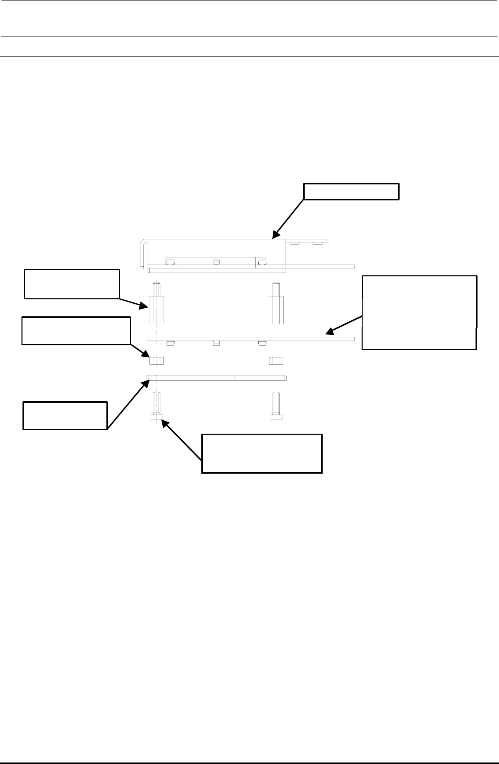
4-7. Replacing the Solder Recognition Light Board
<Procedure>
1) Remove the brazier head screws to detach the PRISM BASE, OCC angle light board, and
board spacers.
2) Reassemble the components in the reverse order of disassembly.
3) After the solder recognition light has been replaced, adjust the OCC light. (See 4-8, List of
Readjustment Items after Replacement.)
HX00335000G
基板スペーサ :4個
角度照明ユニット
HX00354000D
基板スタッド :4個
40032433
低頭ねじ M3×10 :4個
40014043
PRISM BASE
40047508
OCC A LIGHT PCB ASM
取付け向きに注意
(LED面下向き)
Angle light unit
Board stud: 4 pcs.
Board spacer: 4 pcs.
Carefully check the
mounting orientation.
(LED surface faces
downward.)
Brazier head screw
M3 × 10: 4 pcs.
Rev. 1.00
FX-3R Maintenance Guide
4-9
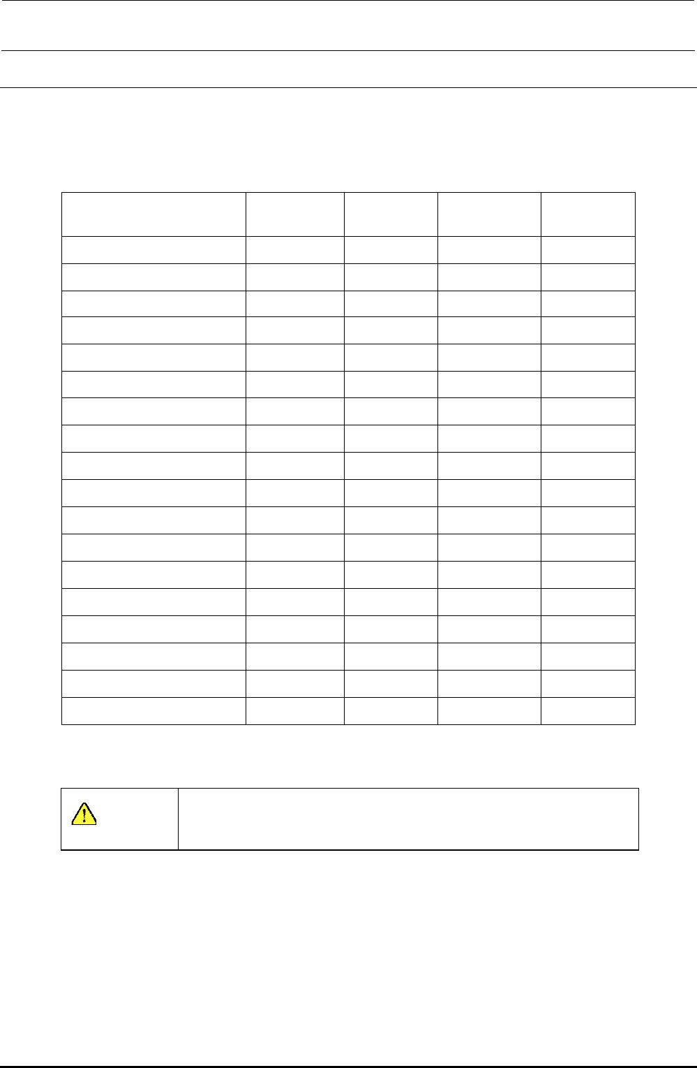
4-8. Readjustment After Replacement of OCC Unit
{: Mandatory U: Check −: Unnecessary
∗: Optional
Table 4-8-1 List of Readjustment Items after Replacement
OCC lens
assembly
OCC light
assembly
Light board
assembly
Lens filter
OCC focus adjustment {
― ― ―
Filter adjustment U {
―
{
Adjustment of OCC light quantity U { { {
Common mark adjustment {
― ― ―
X-beam parallelism check {
― ― ―
OCC offset {
― ― ―
CAL block offset {
― ― ―
CAL piece holder offset {
― ― ―
Head offset {
― ― ―
HMS offset {
― ― ―
BMR offset
∗
{
― ― ―
ATC offset U
― ― ―
AWC offset U
― ― ―
Pick-Up reference position offset U
― ― ―
CVS offset
∗
U
― ― ―
SOT inspect unit
∗
U
― ― ―
Vacuum offset U
― ― ―
General mounting offset {
― ― ―
Input the MS parameters from the top in order.
CAUTION
To prevent any personal injury, do not put your hand inside the
machine or your face or head close to the machine during operation
of the touch panel and/or HOD.
Rev. 1.00
FX-3R Maintenance Guide
5-1
Rev. 1.00
DANGER
To prevent any trouble caused by accidental machine start, always
shut-down the power before starting the maintenance and
adjustment work.
[5] BOARD TRANSPORT UNIT
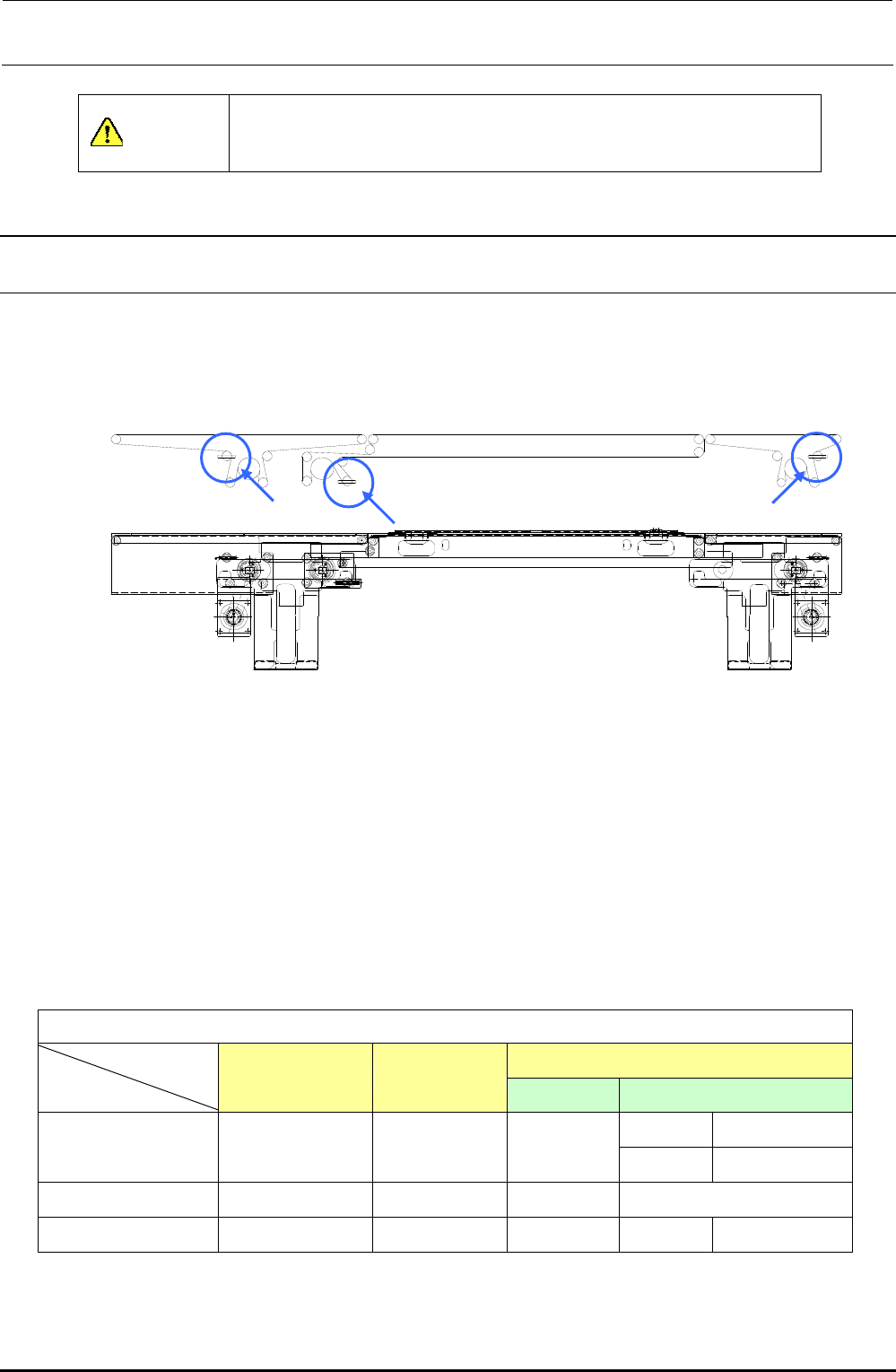
5-1. Replacing the Transport Belt
1) Loosen the transport belt tension adjustment pulley. (Locations indicated by arrows in the
figure below)
Figure 5-1-1 PWB Transport Block and Transport Belt
2) Replace the belt with the one shown in Table 5-1-1.
3) To provide appropriate belt tension, measure the length of the belt with no tension exerted, and
adjust the position of the transport pulley along the slot so that the belt length increases by
0.5%.
<Adjustment procedure>
Use a pencil or similar tool to put two marks, which are 200mm apart from each other, on the belt.
Move the transport pulley to exert tension so that the distance increases to 201 mm.
Table 5-1-1 Transport Belt Part No.
[List of Replacement Parts]
IN/OUT
STATION JOINT
ST Extended transport
150 mm 40073709
L PWB specification
40046935 40046936 40046937
250 mm 40073708
L-wide OP (Note)
40046935 40046936 40046938
−
XL PWB specification
40092069 40092061 40092060 200 mm 40092062
(Note) L-wide is the option specification.
IN/OUT-rail
S-rail
JOINT-rail