fx3r.pdf - 第57页
FX-3R Maintenance Guide 5-4 Rev. 1.00 5-4. Replacing the IN and OUT Sensors Bind the cables A and B with binding bands, taking care that they are not pulle d or loosened excessively during adjustment of sensor position. …
FX-3R Maintenance Guide
5-3
Rev. 1.00
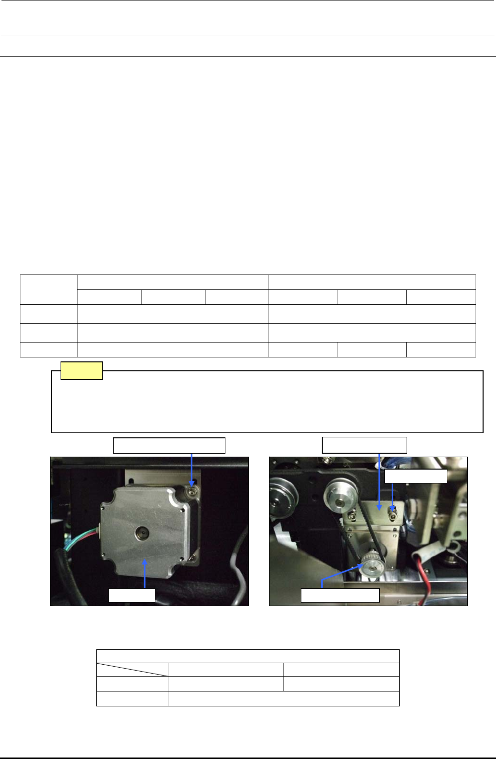
5-3. Replacing the STATION, IN, OUT, and JOINT Motors
1) Disconnect the connector of the motor relay cable.
2) Loosen the screws f fixing the motor bracket d to detach the drive belt from the motor pulley
e.
3) Loosen the motor fixing screws g and detach the motor c.
Reassemble the parts and components in the reverse order of disassembly. (i.e. from step 3) to step
1)). While reassembling, the following adjustment is required.
<Adjustment> For details, see “PWB Transport” in the QA table.
1) The end face of the motor pulley shall be aligned with the end of the motor shaft.
2) Tension adjustment of the timing belt
• Specification value: 17.5 to 21.5N⋅m
Use UNITTA's acoustic belt tension meter for measurement. Enter the following values
to the tension meter and make a measurement:
Table 5-3-1 Transport Motor Tension Adjustment Values
L specification XL specification
STATION IN/OUT JOINT STATION IN/OUT JOINT
Weight 2.5
←
Width 6.0
←
Span 90 90 182 160
Figure 5-3-1 Station Motor (L specification)
Table 5-3-2 Replacement Parts of Transport Motor
[List of Replacement Parts]
STATION/IN/OUT JOINT
L specification 40048074 ∗1 40048075 ∗2
XL specification 40048075
∗1 The transport motor was changed from the motor (E93417290A0) and these motors have the interchangeability.
∗2 The transport motor was changed from the motor (E93408550A0) and these motors have the interchangeability.
Belt (tension) is stretched excessively. → Torque of the drive shaft increases.
Belt (tension) is loosened excessively. → Teeth on the timing pulley are skipped.
(Noise is produced.)
Note
Motor bracket d
Screws f
Motor pulley e
Motor fixing screw g
Motor c
FX-3R Maintenance Guide
5-4
Rev. 1.00
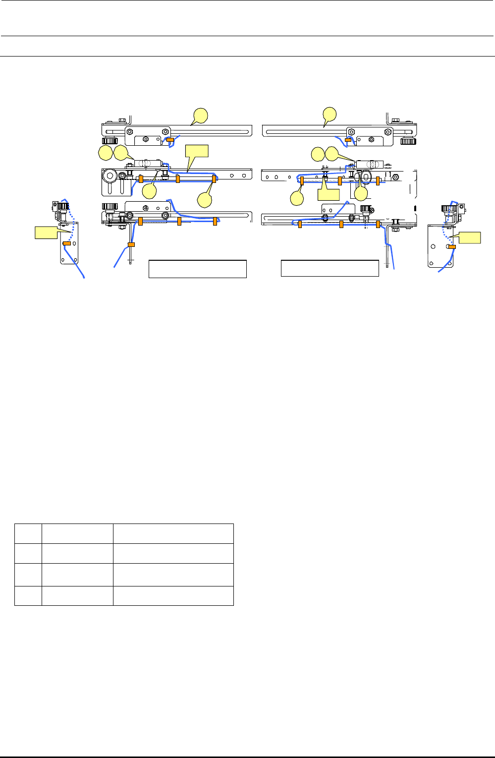
5-4. Replacing the IN and OUT Sensors
Bind the cables A and B with binding bands, taking care that they are not pulled or loosened
excessively during adjustment of sensor position.
Figure 5-4-1 IN and OUT Sensors
<Adjusting the sensitivity>
1) Make an adjustment so that a (matte) black glass epoxy PWB placed on the transport path can
be detected.
2) Place a (matte) black glass epoxy PWB under the sensor and rotate the sensitivity adjustment
knob of the sensor counterclockwise. Then gradually rotate it clockwise up to the position at
which the specified PWB is detected.
∗ If any black glass epoxy PWB is not available, use the PWB having the darkest color of those to
be used.
[List of Replacement Parts]
d
40002208
IN sensor assembly
e
40002210
OUT sensor assembly
f
SL4031291SC
SEMS cap bolt, M3×12
g
EA9500B0000
Tie-up band 60
Table 5-4-1 IN and OUT Sensors
d
c
f
g
e
A
B
Left-side sensor
d
e
c
g
f
B
A
Right-side sensor
FX-3R Maintenance Guide
5-5
Rev. 1.00
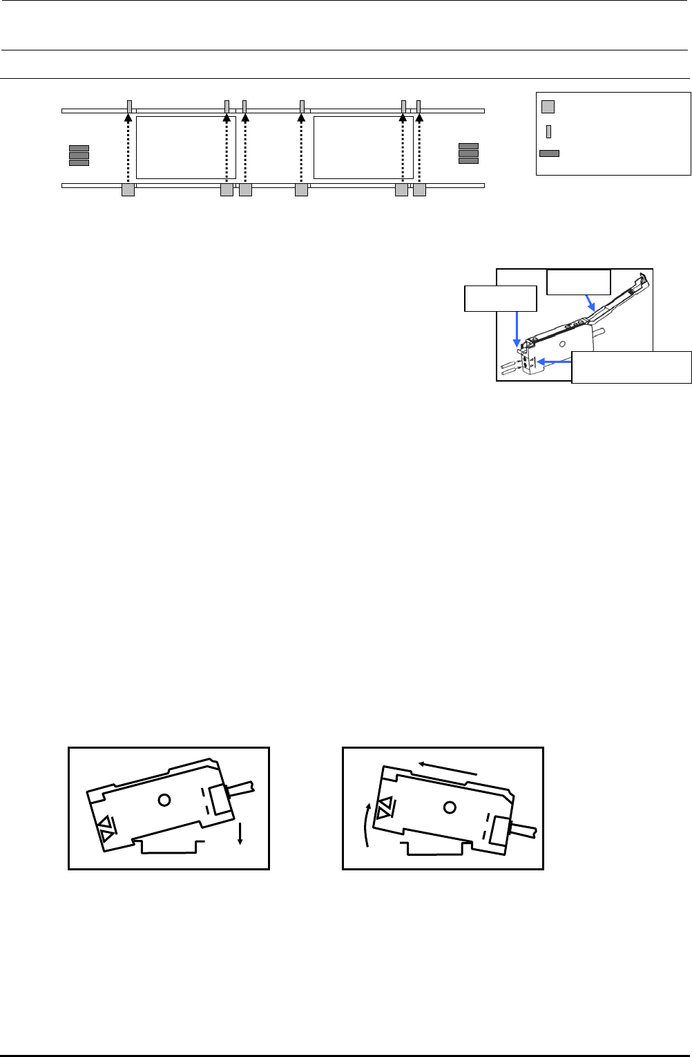
5-5. Replacing the WAIT, STOP, and C-OUT Sensors
Figure 5-5-1 Placement of Sensors (Left → Right Transport)
5-5-1. Replacing the Fiber
1) Remove the fiber from the transport rail.
2) Lay down the fiber fixing lever of the sensor amplifier to pull
out the fiber.
3) Detach the fiber from the WAIT sensor bracket.
4) When installing new fibers, reassemble the
components in the order of step 3) to 1).
∗ Insert the fiber until it reaches the far position of the
amplifier unit. For the fiber insertion length, refer to
the reference mark for the fiber insertion length.
∗ After replacement, perform the steps described in section 5-5-3, "Adjusting the Sensitivity of
the WAIT/STOP/C-OUT Sensor".
5-5-2. Replacing the Amplifier Unit
<How to mount the amplifier unit>
1) Insert the groove (part A) on the front of the amplifier unit into the DIN rail.
2) Push the rear of the amplifier unit (part B) to fit it completely.
<Detaching the amplifier unit>
1) Push the unit strongly forward (c). The front lock is then released.
2) As shown in the Figure, pull up the unit (d) to detach it.
∗ After replacement, perform the steps described in Subsection 5-5-3, "Adjusting the Sensitivity
of the WAIT/STOP/C-OUT Sensor".
L-STATION R-STATION
WAIT-L WAIT-R
STOP-L COUT-L
STOP-R
COUT-R
WAIT-R
STOP-R
COUT-R
WAIT-L
STOP-L
COUT-L
Sensor emitting area
Sensor receiving area
Amplifier
Operation
cove
r
Fiber fixing
leve
r
Fiber insertion length
reference mark
Figure 5-5-1-1 Sensor Amplifier
A
B
Figure 5-5-2-1
Mounting the Sensor Amplifier
d
c
Figure 5-5-2-2
Detaching the Sensor Amplifier