fx3r.pdf - 第76页
FX-3R Maintenance Guide 5-23 Rev. 1.00 5-15. Replacing the Barcode Reader (On-Demand Production, Option for SCS) (1) Functions The barcode reader of the transport unit reads the 1D-barcode of the PWB and transmits the re…
FX-3R Maintenance Guide
5-22
Rev. 1.00
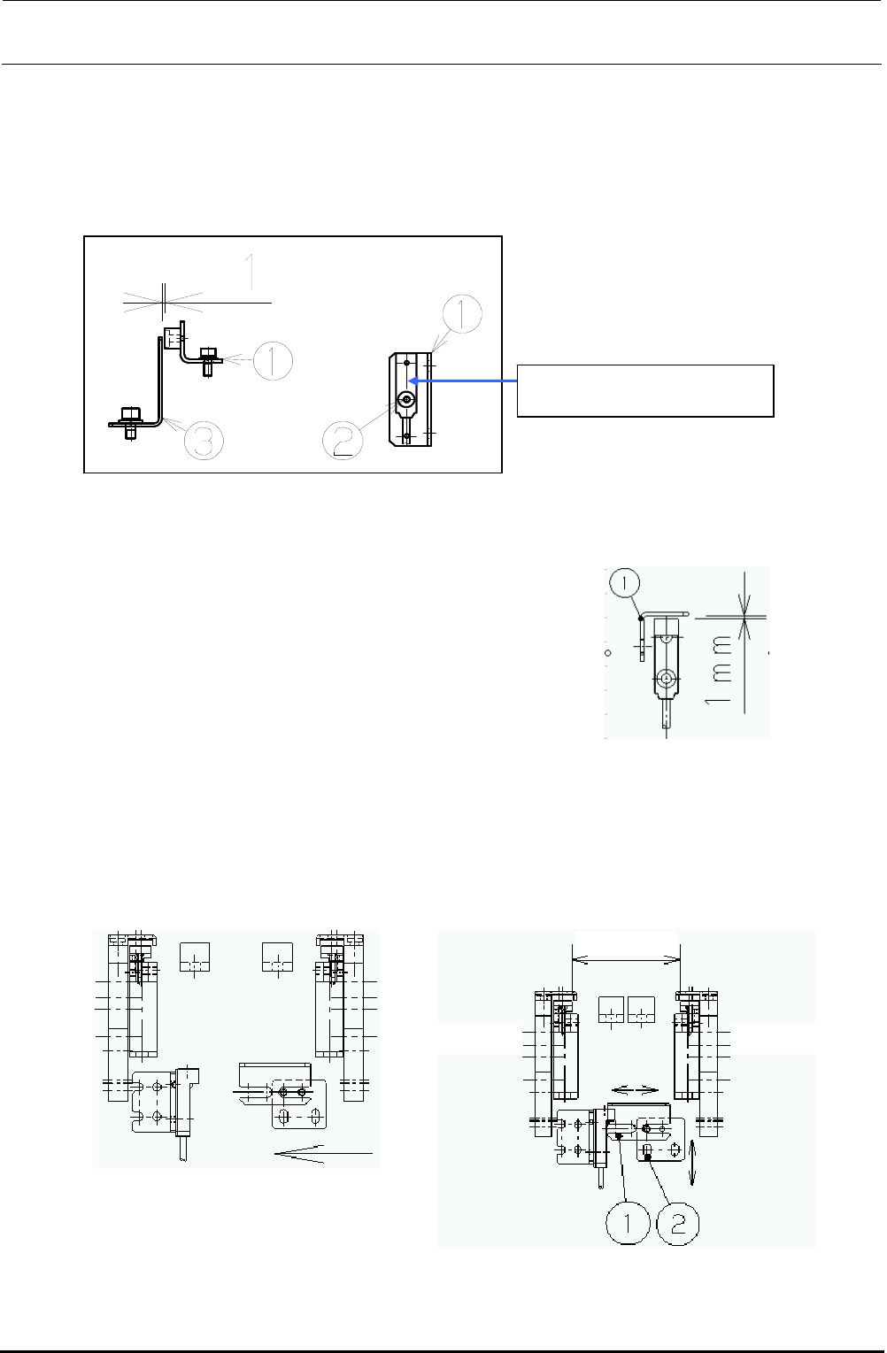
d Move the sensor dog (c) leftward until the
sensor LED goes on. Then bring the dog
closer another 1mm.
Transport
width 50mm
"Reference side"
"Driven side"
5-14-2. Replacing the AWC Origin Sensor
1) Loosen the screw d. Detach the AWC origin sensor from the AWC origin sensor bracket c and
replace it with a new one.
2) Assemble the AWC origin sensor so that the clearance between the AWC sensor dog e and
the AWC origin sensor becomes 1 mm.
Figure 5-14-2-1 AWC Origin Sensor
5-14-3. Replacing the Transport Stopper Interference Sensor
1) Adjust the clearance between the sensor dog and the transport stopper interference sensor to
1 mm.
2) Sensor dog assembling position
Narrow the transport width and gradually bring the sensor dog nearer to the transport stopper
interference sensor. After the sensor is turned on (i.e. the LED goes on), move the dog another
1mm in the direction indicated by the arrow, and fix it there.
Figure 5-14-3-1 Sensor Dog Clearance
c While the power is ON, manually
narrow the transport width while
holding down the EMERGENCY
STOP button.
40002120
AWC Origin Sensor Assembly
FX-3R Maintenance Guide
5-23
Rev. 1.00
5-15. Replacing the Barcode Reader
(On-Demand Production, Option for SCS)
(1) Functions
The barcode reader of the transport unit reads the 1D-barcode of the PWB and transmits the
results to the cPCI-8994 PCB through the RS232C.
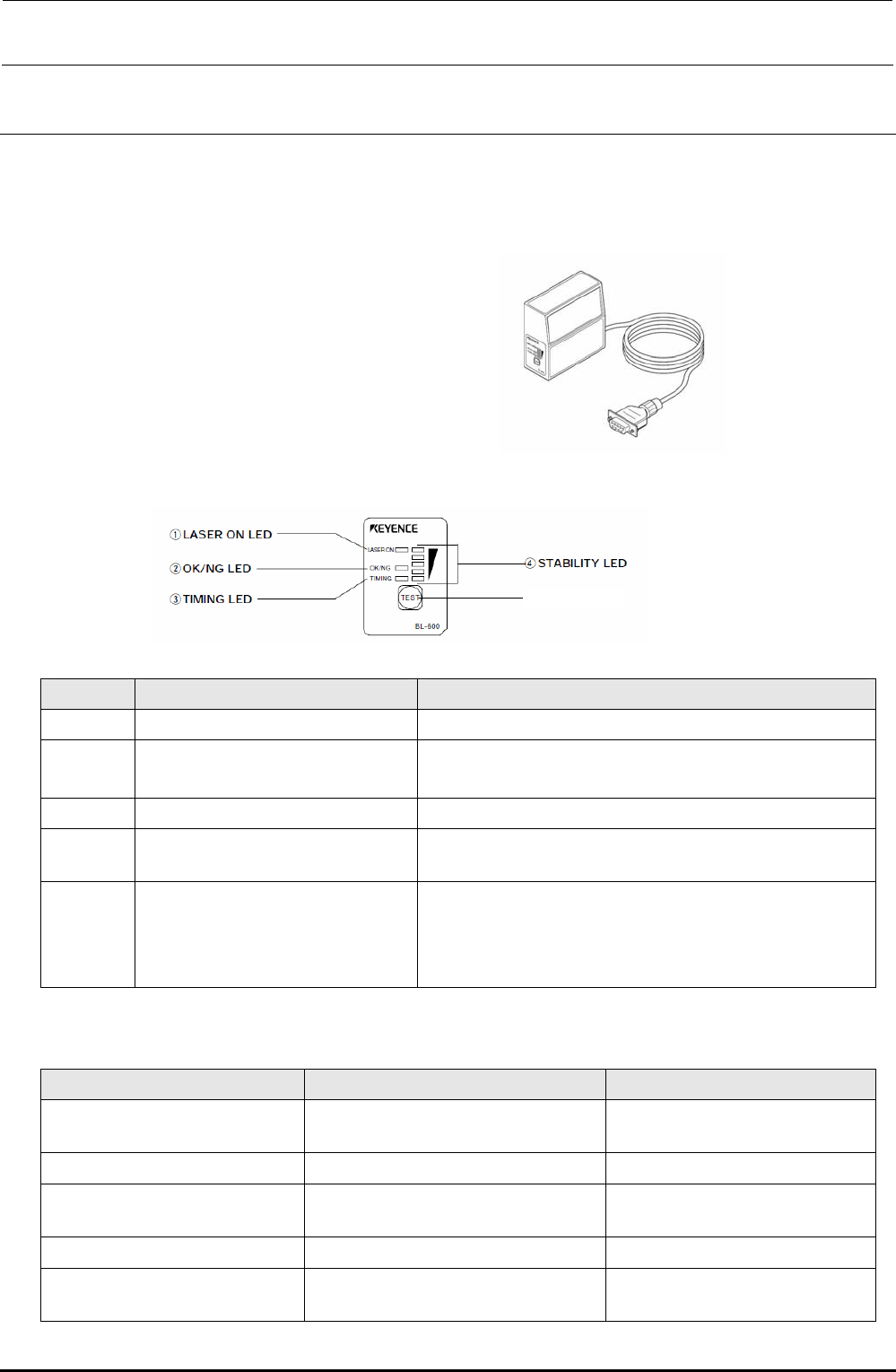
(2) Meaning of LED
No. Name Function
c
LASER ON LED Lit when the laser is output.
d
OK/NG LED
• Lit in green when the OK signal is output.
• Lit in red when the NG signal is output.
e
TIMING LED Lit when the timing input is ON.
f
STABILITY LED
Indicates the reading stability and operation status of the main
unit. (See also the Table below.)
g
TEST switch The following operations can be performed with this switch.
• Test mode is started.
• When this switch is pressed instantaneously (2 sec. or less),
the BL-600-series reads the barcode only once.
STABILITY LED indications in accordance with barcode reader operation status
Barcode reader operation status STABILITY LED indication Remedy
Power is turned ON.
STABILITY LEDs are lit sequentially from
the bottom.
⎯
Setup mode All STABILITY LEDs flash.
⎯
Setting send/receive standby status
The 1st, 3rd, and 5th STABILITY LEDs
from the top flash at the same time.
⎯
Laser forced OFF The bottom STABILITY LED flashes.
⎯
Barcode reader error
Any of the 2nd, 3rd, and 4th STABILITY
LEDs from the top flashes.
The main unit error or power voltage
drop may occur.
g TEST switch
FX-3R Maintenance Guide
5-24
Rev. 1.00
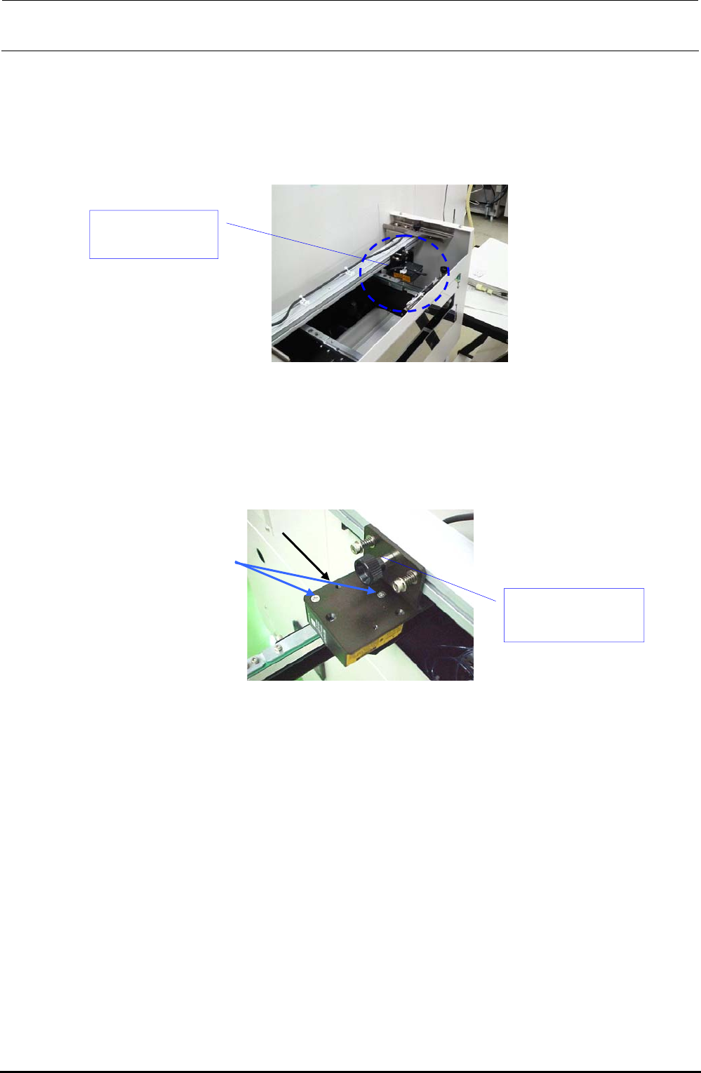
(3) Replacement procedure
The barcode reader (HX006100000) has been assembled to the PWB transport inlet as shown in
the Figure below.
(This Figure shows the left → right transport machine. For the right → left transport machine,
the barcode reader is assembled to a position opposite to that shown in this Figure.)
Figure 5-15-1
1) Remove the flat head screws e (2 pcs.) to detach the BARCODE READER d from the
ROTARY PLATE c.
Figure 5-15-2
2) Cut the tie-up band bundling the barcode reader cables.
Barcode reader
(HX006100000)
e
c
d Barcode reader
(HX006100000)