fx3r.pdf - 第85页
FX-3R Maintenance Guide 8-3 Rev. 1.00 8-1-4. Replacing the Selector Swit ch (Optional Replacement Table) 1) Shut-down the main compressed air to the main unit (with the hand valve). 2) Turn the selector switch cap counte…
FX-3R Maintenance Guide
8-2
8-1-2. Adjusting the Speed Controller of the Bank-Up Cylinder
(Optional Replacement Table)
1) For the speed controllers of the right side
cylinder, adjust those of the fixed and left side
cylinders.
2) The speed controllers have been set so that
the bank-up cylinder completes ascent
operation in 3.8 to 4.2 seconds, descent
operation in 2 to 2.5 seconds. (When
assembled)
• UP speed : To be adjusted by the
upper speed controller.
Upper speed
controller
Lower speed
controller
Figure 8-1-2-1 Back-Up Cylinder
Positions
If the up speed of the left cylinder is too fast,
turn the speed controller adjustment screw
clockwise.
• DOWN speed: To be adjusted by the lower
speed controller.
If the down speed of the left cylinder is too
fast, turn the speed controller adjustment
screw clockwise.
3) If the up and down speeds of the left and right cylinders are the same, lock the adjustment
screws of the speed controllers with the lock screws.
4) After the adjustment screws have been locked, recheck the up and down speeds.
8-1-3. Replacing the Bank-Up Detection Sensor
(Optional Replacement Table)
1) Turn off the power to the main unit.
2) Lower the lifter.
3) Loosen the fixing screws, remove the sensor
and replace it with a new one.
4) Reassemble the components in the reverse
order of disassembly.
<Adjustment>
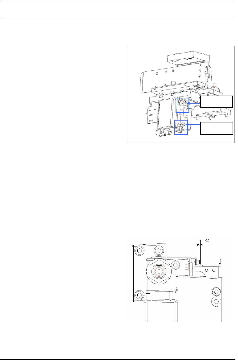
1) Turn on the power to the main unit.
2) Make sure that there is a 0.9mm gap
between the bank sensor dog and sensor
as shown on the right.
Figure 8-1-3-1 Back-Up Detection Sensor
Rev. 1.00
FX-3R Maintenance Guide
8-3
Rev. 1.00
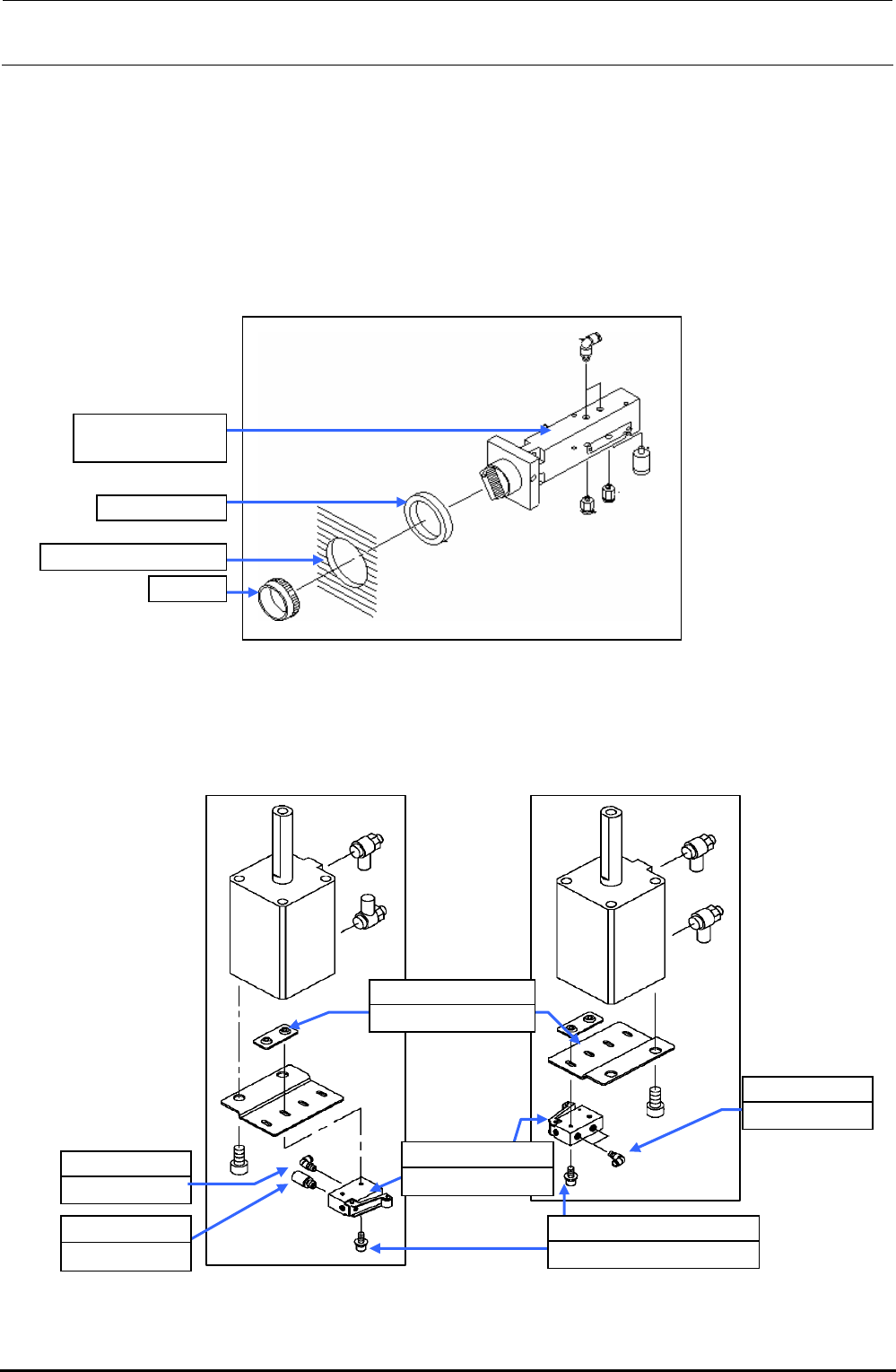
8-1-4. Replacing the Selector Switch (Optional Replacement Table)
1) Shut-down the main compressed air to the main unit (with the hand valve).
2) Turn the selector switch cap counterclockwise to detach the selector switch from the cover.
3) Mount the half-union and silencer on a new selector switch and secure the selector switch to
the cover with the cap.
4) Supply the main compressed air to the main unit.
Figure 8-1-4-1 Selector Switch Assembly (40000585)
8-1-5. Replacing the Roller Lever (Optional Replacement Table)
Before replacing the roller lever, always shut-down the main compressed air.
Cap
Cover mounting hole
Rubber, 3 pcs.
PV0151170A0
Selector switch
PJ304040505
Elbow union
E2811729000
Valve nut plate
PV010505000
Mechanical valve
PJ304040505
Elbow union
PX050501000
Silencer
Roller lever assembly
with silencer
Roller lever assembly
with elbows at both ends
SL6042592TN
SEMS cap bolt M4×25
Figure 8-1-5-1 Roller Lever
FX-3R Maintenance Guide
8-4
8-1-6. Replacing the Cables and Connectors of Replacement Table (For Intelli trolley)
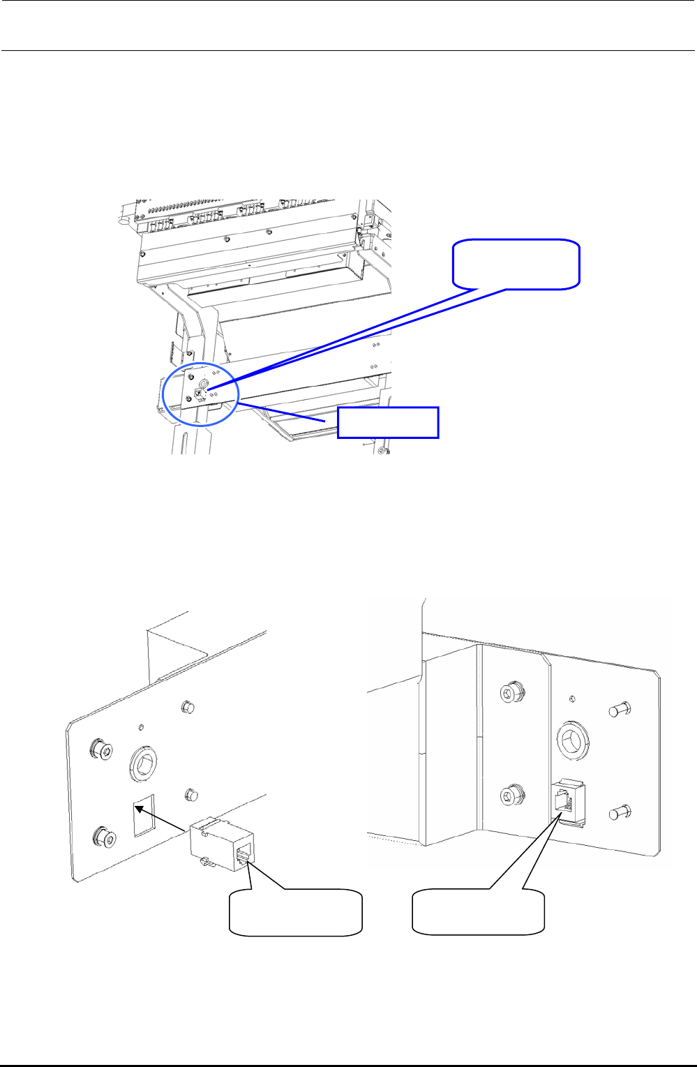
1) Replacing the connector (HK065120060)
c Before replacing the connector, disconnect the cable connected to both ends of the
connector.
Connector
HK065120060
Portion A
Figure 8-1-6-1 Replacement Table when Viewed from Mounter
(From Obliquely downward View Field)
d When mounting the connector, pay special attention to its orientation as shown in the Figure
below.
Mounter side
Lock part faces
downwa
r
d.
Rear side
Lock part faces
u
p
ward.
Figure 8-1-6-2 Enlarged Drawing of Portion A
e Connect the cable to both ends of the connector. (The connector on the mounter side is
located on the OUT side.)
Rev. 1.00