fx3r.pdf - 第88页
FX-3R Maintenance Guide 8-6 8-1-7. Replacing the Antenna of the Re placem ent Table (For Intelli trolley ) 1) Disconnect the cable from the connector of the antenna array. Antenna array 40073664 RFID JOINT CABLE ASM 4007…
FX-3R Maintenance Guide
8-5
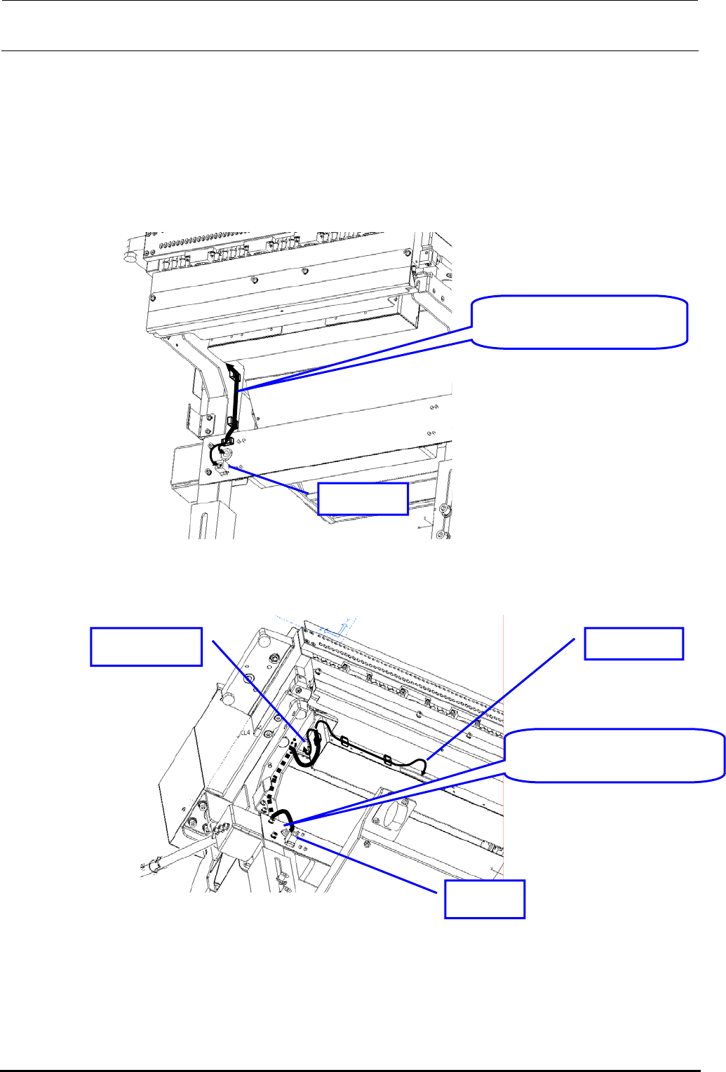
2) Replacing the cable (RFID JOINT CABLE ASM: 40079659)
c Before replacing the cable, disconnect the cable connection from the antenna and relay
connector.
d Disconnect the cable from the cable securing materials (cable band and cable clamp).
e After the cable has been replaced, secure the cable and connect it to the connector in the
original manner.
RFID JOINT CABLE ASM:
40079659
OUT side
Figure 8-1-6-3 Cable Wiring Diagram 1
RFID JOINT CABLE ASM:
40079659
IN side
RFID side Antenna side
Figure 8-1-6-4 Cable Wiring Diagram 2
Rev. 1.00
FX-3R Maintenance Guide
8-6
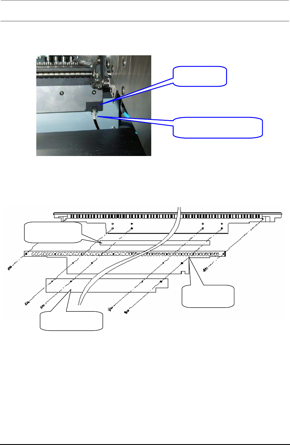
8-1-7. Replacing the Antenna of the Replacement Table (For Intelli trolley)
1) Disconnect the cable from the connector of the antenna array.
Antenna array
40073664
RFID JOINT CABLE ASM
40079659
Figure 8-1-7-1 Replacement Table when Viewed from the Front (Feeder Insertion Side)
2) Remove the screws (6 pcs.) securing the antenna array.
Antenna array
40073664
Conductive tape
HX002680000
Shield bracket 60
40081207
Figure 8-1-7-2 Antenna Array Assembling Drawing
Rev. 1.00
FX-3R Maintenance Guide
8-7
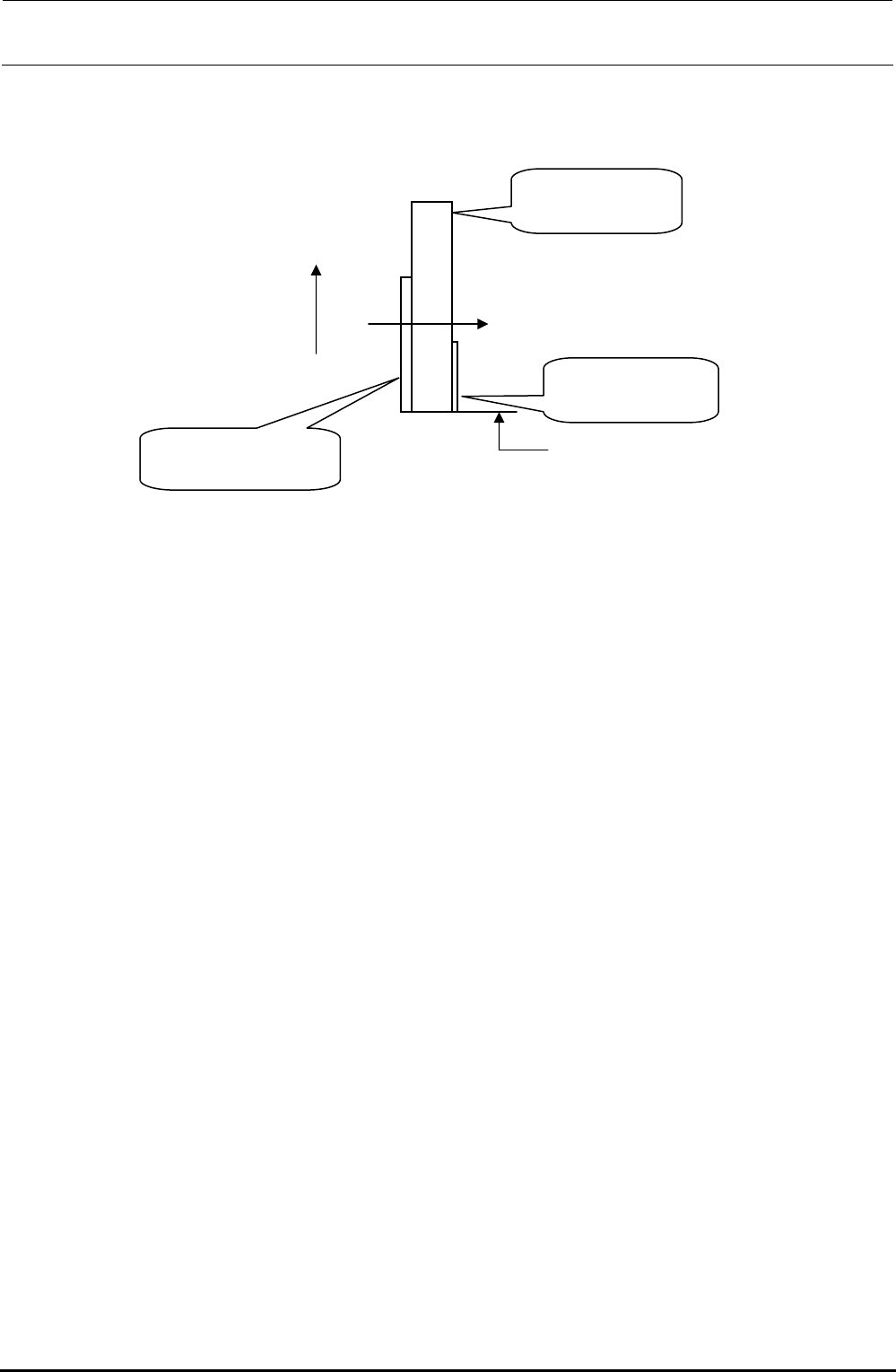
3) When mounting the antenna array, mount it so that the positional relationship is as follows.
Note that it is not allowed to reuse the conductive tape (HX002680000).
UP
Tightening direction
Make the tape matched
with the lower end position.
Shield bracket 60
40081207
Antenna array
40073664
Conductive tape
HX002680000
Figure 8-1-7-3 Cautions on Antenna Array Assembly
4) After the replacement has been completed, connect the antenna to the mounter or Intelli trolley
pool and make sure that the CH∗ LED on the MPC connected flashes.
Rev. 1.00