265ProFlow.pdf - 第14页
TECHNIC AL RE FERENCE PNEUMA TIC SC HEMATICS 1.10 ProFlow Manual Chapter Issue 8 Dec 02 T yphoon Machines ProFlow Pneumatic Actuators Software Controlled Air Regulator (SCAR) Mains Air In Silencers Manifold A B 5/2 Solen…
TECHNICAL REFERENCE
PNEUMATIC SCHEMATICS
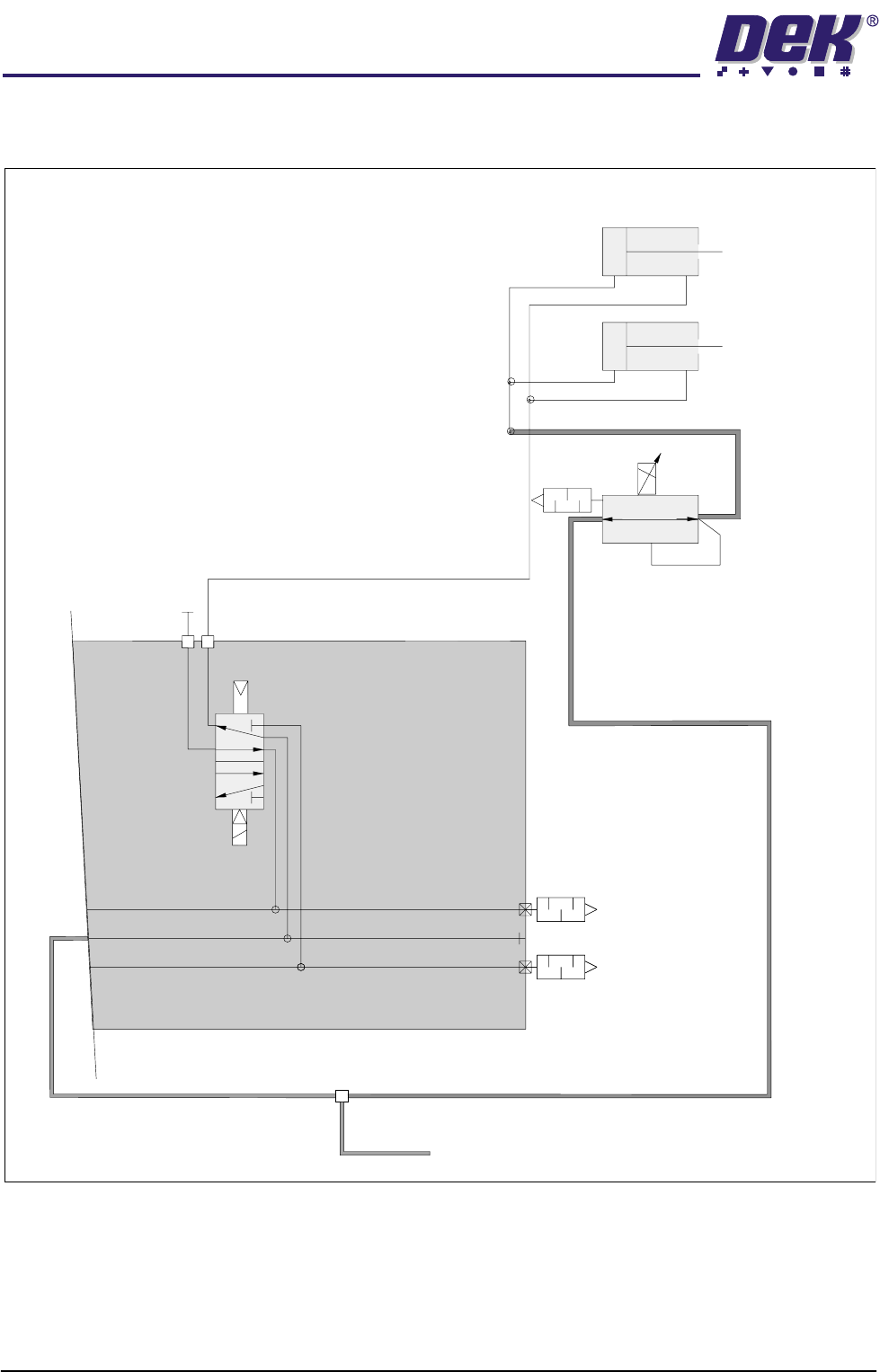
Chapter Issue 8 Dec 02 ProFlow Manual 1.9
PNEUMATIC SCHEMATICS
GSX & Lt Machines
Mains Air In
Manifold
Solenoid
A
B
P
R
R
Silencers
ProFlow
Pneumatic
Actuators
Software Controlled
Air Regulator
(SCAR)
TECHNICAL REFERENCE
PNEUMATIC SCHEMATICS
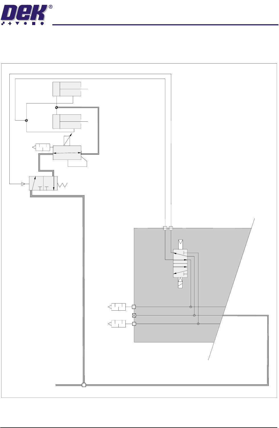
1.10 ProFlow Manual Chapter Issue 8 Dec 02
Typhoon Machines
ProFlow
Pneumatic
Actuators
Software Controlled
Air Regulator
(SCAR)
Mains Air In
Silencers
Manifold
A
B
5/2
Solenoid
TECHNICAL REFERENCE
MECHANICAL DETAIL
Chapter Issue 8 Dec 02 ProFlow Manual 1.11
MECHANICAL DETAIL
General On GSX, Lt and Infinity machines the ProFlow unit is fitted to the rear squeegee
mounting position, the ProFlow downstop is fitted to the front squeegee mount-
ing position, when the ’I’ bars have been removed. On fixed head machines the
ProFlow unit is fitted to the printhead mechanism by means of two securing
bolts.
ProFlow Pressure
Mechanism
The primary function of the pressure mechanism is to provide an adjustable
downward force (pneumatic pressure) onto the transfer head paste system.
This pressure (paste pressure) is set by software control, (refer to Pneumatic
Supply paragraph of this section and Adjustments and Settings section of this
chapter for further information).
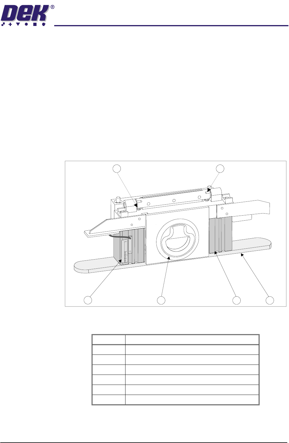
Details of the pressure mechanism elements are listed in the Pressure Mecha-
nism Elements figure and table below.
Figure 1-5 Pressure Mechanism Elements (cover removed)
Item Description
1 Hinge Recess (2 Positions)
2 Piston Crosshead
3 Pneumatic Actuators (2 Positions)
4 Flush Pull Latch
5 Cassette Low Sensor
6 Spring Plunger (2 Positions)
3
2
1
4
5
6
15
0
30