265ProFlow.pdf - 第17页
TECHNI CAL REFEREN CE MECH ANICA L DETAIL Chapter Issue 8 Dec 02 ProFlow Manual 1.13 Cassette T ransfer Head The functi on of the cassett e transf er head option i s to transf er pri nt material from the cassette unit an…
TECHNICAL REFERENCE
MECHANICAL DETAIL
1.12 ProFlow Manual Chapter Issue 8 Dec 02
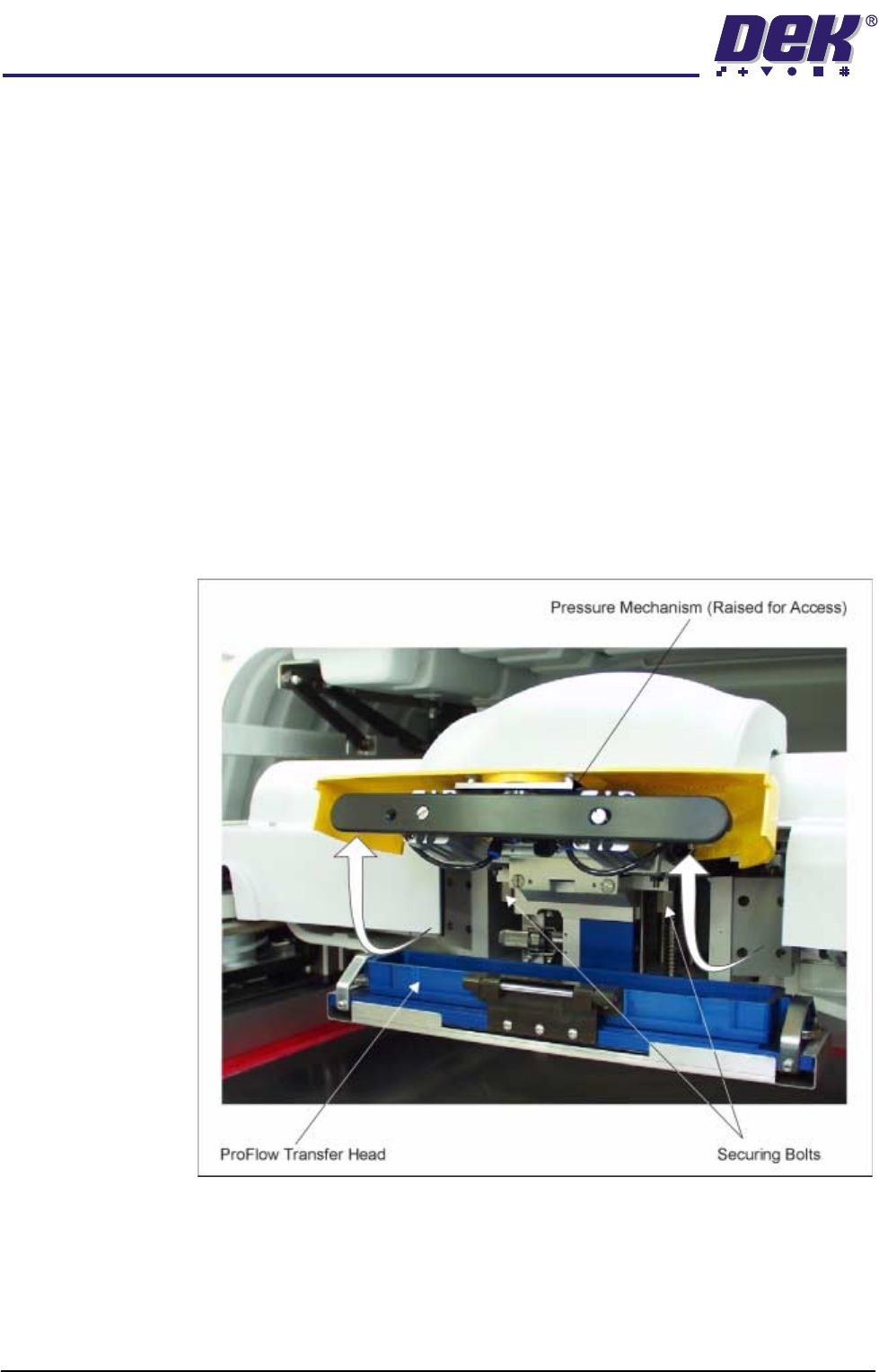
The ProFlow pressure mechanism is fitted to the printhead drive mechanism
bearing block by the two securing bolts, Figure - Pressure Mechanism Raised
for Access below refers.
NOTE
Prior to fitting the ProFlow unit to GSX, Lt or Infinity machines, ensure that both
the front and rear squeegee supports (’I’ bars) are removed.
Prior to fitting the ProFlow unit to fixed head machines, ensure that the correct
(ProFlow) printhead mechanism is fitted to the print carriage, refer to Replace-
ment Procedures section for further details.
Access for the fitting of the ProFlow transfer head and replacement of the
optional cassette is made by pulling the flush pull latch on the pressure
mechanism. The pressure mechanism is swung on a hinge upwards and is held
in the raised position by means of spring plungers locking into the hinge pin
recesses, (Pressure Mechanism Elements figure refers).
NOTE
The figure below shows an Infinity machine, but the relevant information is valid
for GSX, Lt and fixed head machines also.
Figure 1-6 Pressure Mechanism Raised for Access
TECHNICAL REFERENCE
MECHANICAL DETAIL
Chapter Issue 8 Dec 02 ProFlow Manual 1.13
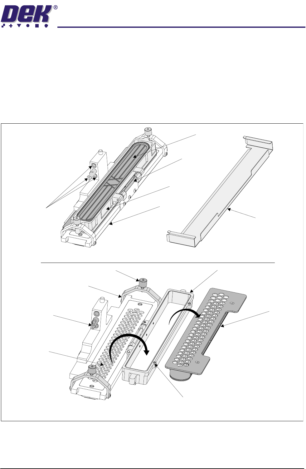
Cassette Transfer
Head
The function of the cassette transfer head option is to transfer print material from
the cassette unit and onto a board as ProFlow moves across the stencil.
The cassette type transfer head comprises the following:
• Conditioning Chamber (single or dual chamber)
• Cassette Carrier Unit
• 300mm Cassette
• Retention System (see Paste Retention System Figure for detail)
Figure 1-7 ProFlow Transfer Head
Pressure Mechanism
Locating Dowel
and Holes
Carrier Unit
Hinged
Bracket
Cassette
Conditioning
Chamber
Chassis Dowel
Carrier UnitThumbscrew (2 positions)
Clamp Bracket (2 positions)
Primary Grid
(removable)
ProFlow Transfer Head Assembly with Cover
Transfer Head Assembly Opened for Access
Cover
Cassette
Cassette Retaining Pin (2 positions)
TECHNICAL REFERENCE
MECHANICAL DETAIL
1.14 ProFlow Manual Chapter Issue 8 Dec 02
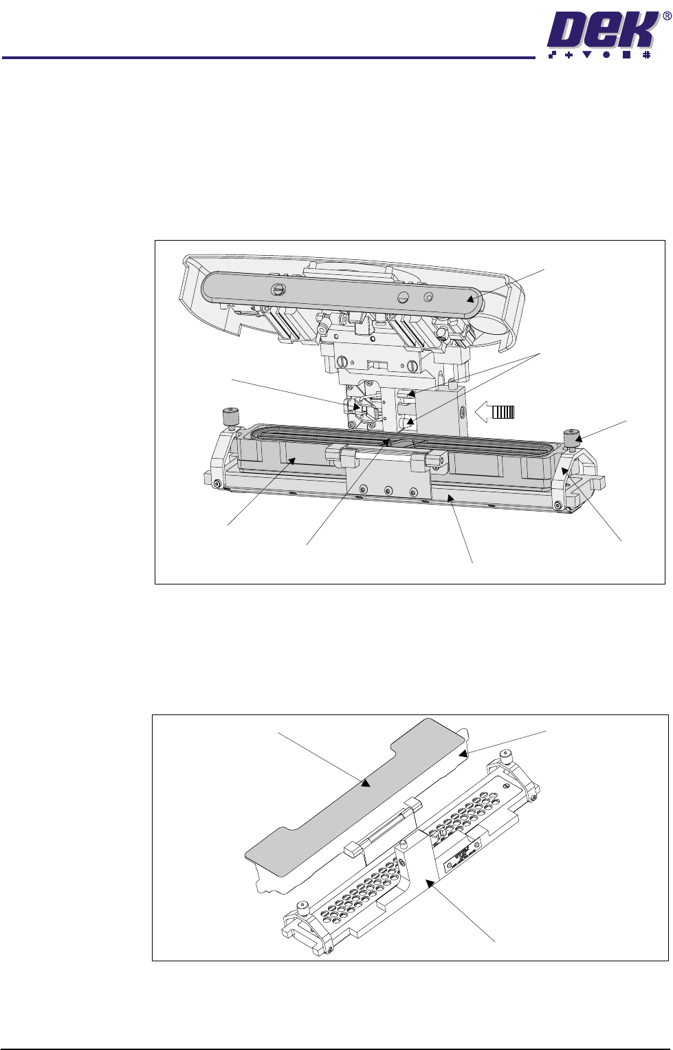
The transfer head is removable from the pressure mechanism unit. Two
locating dowels are used to slide the unit onto the pressure mechanism. Once
the unit is slid fully home, it is secured by closing the locking clip.
NOTE
When the transfer head is loaded with material, ensure that the cover is fitted
when the ProFlow unit is not in use. The cover must be removed prior to print
operation.
Figure 1-8 Transfer Head to Pressure Mechanism Interface
Transfer Head
Size Option
To enable the ProFlow to effectively print on wider boards, the cassette style
transfer head is supplied in three different size options of 300 mm; 350 mm; and
400 mm. The 300 mm size cassette is used with all of these options. (Transfer
Head Table in the Module Overview section refers.)
Figure 1-9 Transfer Head (350mm)
Pressure Mechanism
(raised position)
Locking Clip
Thumbscrew
(2 positions)
Carrier Unit
Cassette
Conditioning Chamber
Clamp Bracket
(2 positions)
Pressure Mechanism
Locating Dowels
(2 positions)
300mm Cassette
350mm Transfer Head Unit
Carrier Unit