265ProFlow.pdf - 第19页
TECHNI CAL REFEREN CE MECH ANICA L DETAIL Chapter Issue 8 Dec 02 ProFlow Manual 1.15 Conditioning Chamber The ProFlow t ransfer head contains a condi tioning chamber for maintain ing the conditi on of th e print mater ia…
TECHNICAL REFERENCE
MECHANICAL DETAIL
1.14 ProFlow Manual Chapter Issue 8 Dec 02
The transfer head is removable from the pressure mechanism unit. Two
locating dowels are used to slide the unit onto the pressure mechanism. Once
the unit is slid fully home, it is secured by closing the locking clip.
NOTE
When the transfer head is loaded with material, ensure that the cover is fitted
when the ProFlow unit is not in use. The cover must be removed prior to print
operation.
Figure 1-8 Transfer Head to Pressure Mechanism Interface
Transfer Head
Size Option
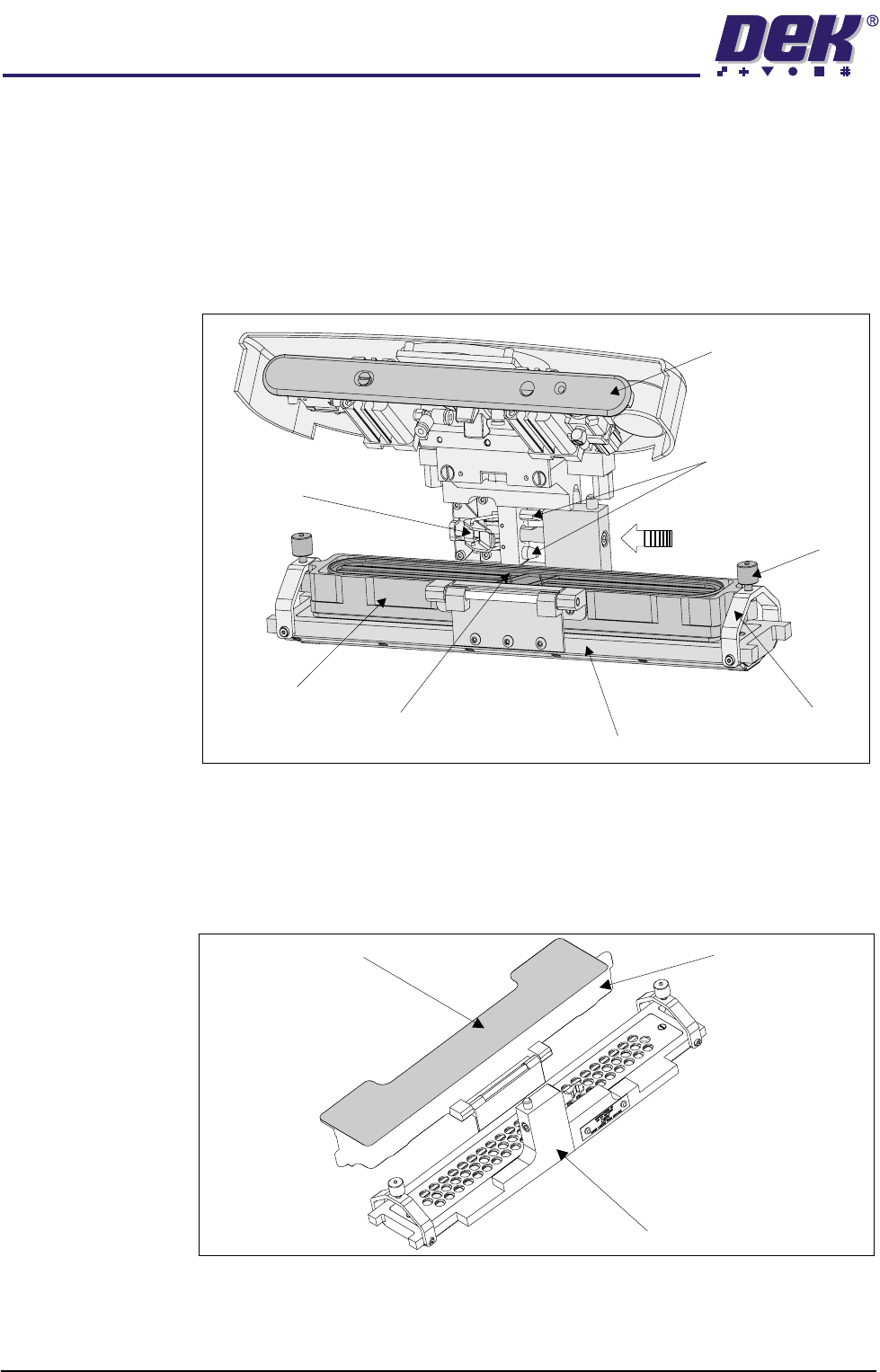
To enable the ProFlow to effectively print on wider boards, the cassette style
transfer head is supplied in three different size options of 300 mm; 350 mm; and
400 mm. The 300 mm size cassette is used with all of these options. (Transfer
Head Table in the Module Overview section refers.)
Figure 1-9 Transfer Head (350mm)
Pressure Mechanism
(raised position)
Locking Clip
Thumbscrew
(2 positions)
Carrier Unit
Cassette
Conditioning Chamber
Clamp Bracket
(2 positions)
Pressure Mechanism
Locating Dowels
(2 positions)
300mm Cassette
350mm Transfer Head Unit
Carrier Unit
TECHNICAL REFERENCE
MECHANICAL DETAIL
Chapter Issue 8 Dec 02 ProFlow Manual 1.15
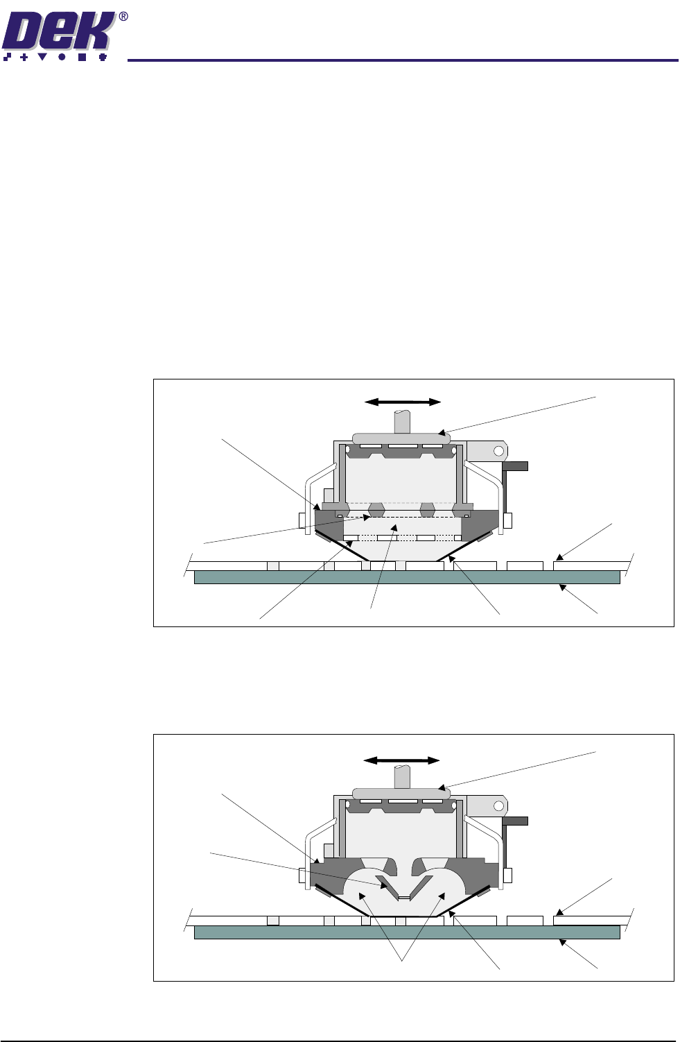
Conditioning
Chamber
The ProFlow transfer head contains a conditioning chamber for maintaining the
condition of the print material. This chamber can be accessed by removing the
primary grid, which is accessible whilst the carrier unit is in the open position.
The grid is sealed onto the conditioning chamber by means of two M4 counter-
sunk screws and ‘O’ ring which fits into the transfer head (ProFlow Transfer
Head Figure refers). There are two types of conditioning chamber for both the
cassette carrier unit and rechargeable unit, as follows:
• Single Conditioning Chamber
• Dual Conditioning Chamber
Single Conditioning
Chamber
The single conditioning chamber, ensures maximum print material optimization
on conventional SMT PCBs printing, the printing material is driven around the
conditioning chamber and bottom chamber by the action of the adhesive nature
of the printing material to the stencil, while the transfer head traverses the
image.
Dual Conditioning
Chamber
The dual conditioning chamber, was partly developed from knowledge gained
with the single conditioning chamber. This ensures maximum print material
transfer and optimization on more demanding process platforms, the print
material is driven around the two individual side chambers, in the same manner
as above.
Transfer
Head
Stencil
BoardWiper
ProFlow Movement (Y Axis)
Piston
Crosshead
Print Material
Conditioning Chamber
Secondary Grid
Primary
Grid
Transfer
Head
Stencil
BoardWiper
Piston
Crosshead
Side Chambers
Nozzle
ProFlow Movement (Y Axis)
Print Material
TECHNICAL REFERENCE
MECHANICAL DETAIL
1.16 ProFlow Manual Chapter Issue 8 Dec 02
NOTE
For ease of identification, all transfer heads with single conditioning chambers
are coloured black and all transfer heads with dual conditioning chambers are
coloured blue.
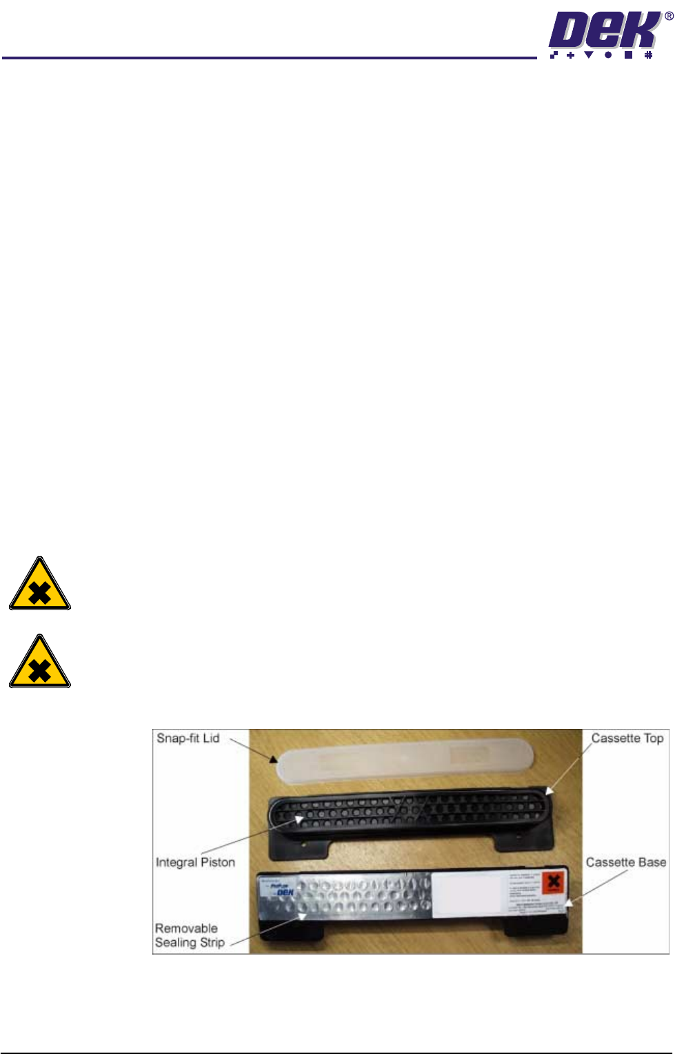
Cassette Carrier The cassette carrier unit is attached to the conditioning chamber by a hinged
bracket, this is swung open when fitting the cassette into place (ProFlow
Transfer Head figure refers).
The cassette is located within the carrier by means of integral ribs and two
retaining pins.
NOTE
When loading a cassette, before the carrier is swung back onto the conditioning
chamber, the cassette sealing strip must be removed.
Two clamp brackets at each end of the transfer head are latched over the carrier
and cassette, these are secured by tightening the thumbscrews into the carrier
dimples.
The cover is fitted to the underside of the ProFlow transfer head during periods
when the ProFlow unit is not in use. This seals any exposed printing material
from the atmosphere and also prevents inadvertent seepage or spills onto the
stencil.
Cassette The 300mm ProFlow cassette capacity is between 800g and 850g of solder
paste.
WARNING
SOLDER PASTE AND SOLVENTS. WHEN USING OR HANDLING ANY SOLDER
PASTE OR SOLVENT FORMULATION THE MANUFACTURERS’ RECOMMEND
SAFETY PRECAUTIONS MUST BE STRICTLY ADHERED TO.
WARNING
PROTECTIVE CLOTHING. APPROVED PROTECTIVE CLOTHING SHOULD BE
WORN BY SOLDER PASTE AND SOLVENT HANDLERS AT ALL TIMES TO
ELIMINATE FUME INHALATION, EYE CONTACT, SKIN CONTACT AND
INGESTION.
Figure 1-10 Cassette Overview