265ProFlow.pdf - 第23页
TECHNI CAL REFEREN CE MECH ANICA L DETAIL Chapter Issue 8 Dec 02 ProFlow Manual 1.19 Rechargeable T ransfe r Head The rechargeabl e transfer head option is fully c om pati ble with t he ProFlo w hardware and of fers the …
TECHNICAL REFERENCE
MECHANICAL DETAIL
1.18 ProFlow Manual Chapter Issue 8 Dec 02
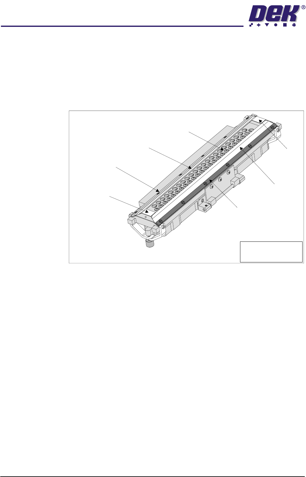
Retention System The retention system, is sited on the underside of the transfer head and consists
of:
• Secondary Grid - stainless steel (Single Conditioning Chamber Units only)
• Wipers - 200/300 titanium coated step edged (2 positions)
• Skis - Vulcanized Rubber (2 positions)
• Wiper Retaining Strips (2 positions)
Figure 1-12 Retention System
Maintenance In order to maintain and clean the unit, all items of the retention system can be
easily dismantled. Wipers and skis are inevitably prone to wear over prolonged
use.
300 micron titanium wipers are available where additional ProFlow system
pressure transfer is required. These are available for all transfer head sizes.
For ink/adhesive printing, mylar wipers are available for all transfer head sizes.
A specially designed transfer head maintenance stand is supplied with ProFlow
to be used during cleaning and maintenance operations of the retention system.
Information on the removal and replacement of these items is detailed in the
Consumable Replenishments chapter of the machine manual.
Wiper
Secondary Grid (Stainless Steel)
Wiper
Wiper Retaining Strip
Wiper Retaining Strip
Ski
Ski
Transfer Head Inverted
Note
Single conditioning unit
type transfer head.
TECHNICAL REFERENCE
MECHANICAL DETAIL
Chapter Issue 8 Dec 02 ProFlow Manual 1.19
Rechargeable
Transfer Head
The rechargeable transfer head option is fully compatible with the ProFlow
hardware and offers the alternative of using ProFlow without changing the
format new material is supplied in, ie material not in ProFlow cassettes can still
be used with ProFlow.
Elements of the rechargeable transfer head comprise:
• Conditioning Chamber (single or dual chamber)
• Diaphragm Retainer
• Diaphragm
• Filling Ports (3 in number, 1 for 150mm transfer head)
• Retention System
• Cover
• Recharging Nozzles (2 in number)
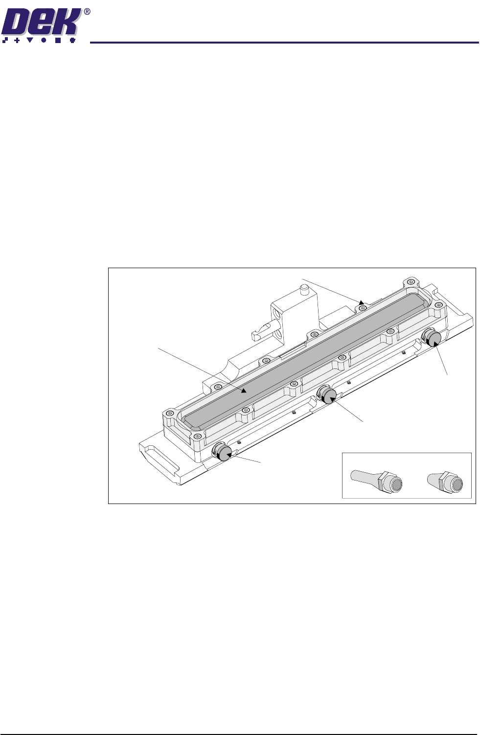
Figure 1-13 Rechargeable Transfer Head
The rechargeable transfer head is constructed in much the same way as the
cassette transfer head. The main difference being that a diaphragm, held in
position by a diaphragm retainer, replaces the cassette. The transfer head is
fitted to the pressure mechanism unit in the same way as the cassette transfer
head unit, (Cassette Transfer Head section of this chapter refers).
Print material is initially filled into the paste chamber through the stainless steel
grid of the retention system (single conditioning chamber units), or the nozzle
system of the dual conditioning chamber type. General recharging is performed
by using the 3 filling ports sited on the front side of the transfer head. The filling
ports are sealed using bayonet connector caps.
NOTE
For detailed procedures of print material filling refer to the Consumable Replen-
ishments chapter of the machine manual or the ProFlow Best Working Practices
guide (DEK Part No. 171280).
Filling Port
Bayonet Cap
Diaphragm
Diaphragm Retainer
Recharging Nozzles
Filling Port
Bayonet Cap
Filling Port
Bayonet Cap
Transfer Head (Showing Diaphragm)
TECHNICAL REFERENCE
MECHANICAL DETAIL
1.20 ProFlow Manual Chapter Issue 8 Dec 02
Recharging Recharging the rechargeable transfer head is carried out using the following
standard cartridge:
• 'Semco' type - 500g or 1kg sizes
NOTE
Maximum cartridge diameter should not exceed 43.6mm
These cartridges are utilized by using either of the following:
• Manual 'Mastic' Gun
• Pneumatic Gun (optional)
NOTE
When using a 500g cartridge, an adaptor (supplied) is fitted between the
cartridge and rear of the gun.
WARNING
SOLDER PASTE AND SOLVENTS. WHEN USING OR HANDLING ANY SOLDER
PASTE OR SOLVENT FORMULATION THE MANUFACTURERS’ RECOMMEND
SAFETY PRECAUTIONS MUST BE STRICTLY ADHERED TO.
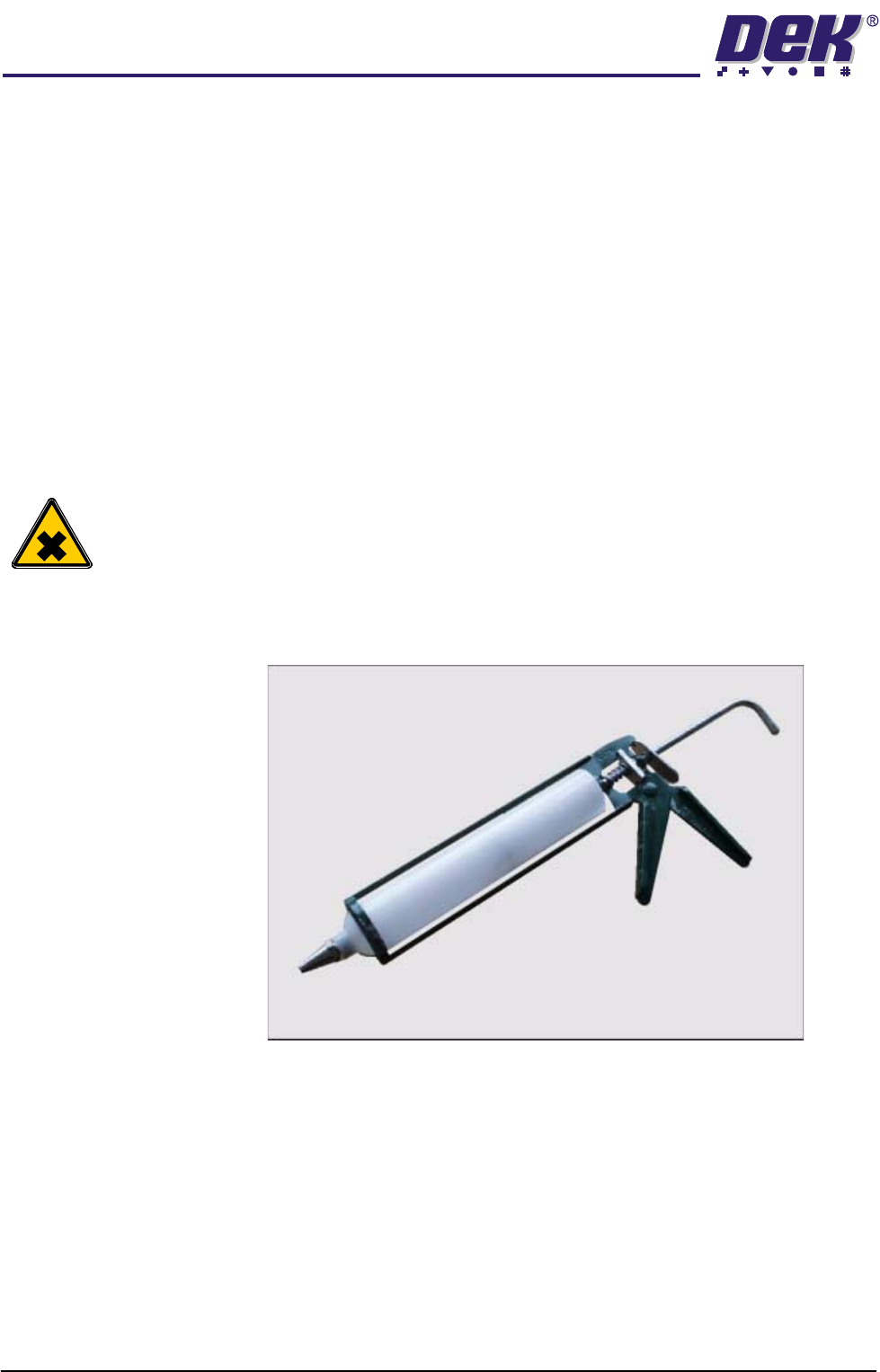
Manual Mastic Gun The standard cartridge, as listed above, can be fitted to a general purpose
mastic gun as shown in the Mastic Gun and Cartridge figure.
Figure 1-14 Mastic Gun and Cartridge
NOTE
For detailed procedures of print material filling refer to the Consumable Replen-
ishments chapter of the machine manual or the ProFlow Best Working Practices
guide (DEK Part No. 171280).