265ProFlow.pdf - 第57页
TECHNI CAL REFEREN CE REPLACEM ENT PROC EDURES Chapter Issue 8 Dec 02 ProFlow Manual 1.53 c. In Diagnost ics the ProFlow menu p age can be acc essed. 6. Carry out the ProFlow Cont act Position Setup in th e Calibrations …
TECHNICAL REFERENCE
REPLACEMENT PROCEDURES
1.52 ProFlow Manual Chapter Issue 8 Dec 02
3. Locate and fit the ProFlow transfer head unit to the pressure mechanism by
means of the two locating dowels. Slide the unit onto the pressure mecha-
nism. Once the unit is slid fully home, it is secured by closing the locking clip.
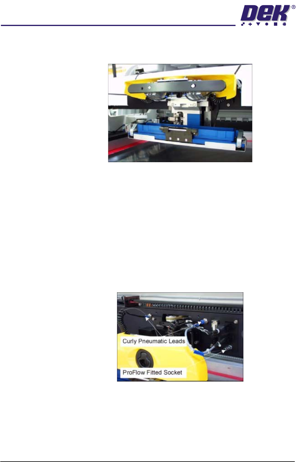
4. Lift the light shroud for access (if fitted) and plug the electrical connection
ProFlow Fitted from the ProFlow unit into the socket sited on the right hand
side of the ProFlow on the print carriage, (figure below refers).
CAUTION
ELECTRICAL CONNECTION.
This electrical connection informs the
machine of ProFlow fitment and must always be connected whilst the
ProFlow unit is fitted otherwise damage may occur if machine is run.
Connect the curly pneumatic leads from the pressure mechanism to each
respective left and right pneumatic connector sited either side of the ProFlow
printhead mechanism (figure below refers).
NOTE
If the squeegee paste dispenser option is fitted to the print carriage, before
using ProFlow, ensure that the paste dispenser regulator gauge reads '0'
pressure.
5. Connect the pneumatics and switch the machine to ON. To ensure that the
machine recognizes the ProFlow module, the following indications on the
machine MMI are evident:
a. During the boot up sequence the operator is prompted to fit the ‘ProFlow
cover’.
b. The soft key that previously indicated ‘Paste Load’ now indicates
‘Knead Paste’.

TECHNICAL REFERENCE
REPLACEMENT PROCEDURES
Chapter Issue 8 Dec 02 ProFlow Manual 1.53
c. In Diagnostics the ProFlow menu page can be accessed.
6. Carry out the ProFlow Contact Position Setup in the Calibrations section
later in this chapter.
7. Select Setup on the MMI. Select Load Data and load the product file to be
printed.
NOTE
For an existing product, the product file has already been written. If the
product is new, either edit an existing or default file. (The Machine Program-
ming Chapter of the User Manual refers.)
8. If the loaded file is the correct file for the product this completes Squeegees
to ProFlow Replacement. If the loaded file has to be edited, proceed with
Step 9.
9. Select Edit Data on the MMI and adjust the following ProFlow parameters
as appropriate:
• Transfer Head Size
• Stencil Protection
• System Pressure
• Idle Paste Pressure
• Knead Paste Pressure
• Knead Off-image
• Knead Before Print
• Clean After Knead
• Knead After Replenish
If Advanced ProFlow is set to enabled, adjust the following ProFlow param-
eters as appropriate:
• FWD Start Speed
• FWD End Speed
• RWD Start Speed
• RWD End Speed
• FWD Start Pressure
• FWD End Pressure
• RWD Start Pressure
• RWD End Pressure
If Advanced ProFlow is set to disabled, adjust the following ProFlow param-
eters as appropriate:
• Front Print Speed
• Rear Print Speed
• Print Paste Pressure
TECHNICAL REFERENCE
REPLACEMENT PROCEDURES
1.54 ProFlow Manual Chapter Issue 8 Dec 02
NOTE
Information on the ProFlow parameters are detailed under Menu Parame-
ters in the Machine Programming chapter of the User manual.
Information on the machine set up procedures are detailed in the Machine
Programming chapter of the User manual.
Drive Belt
Replacement
(fixed head
machines)
To replace the ProFlow drive belt the printhead mechanism must first be
removed from the print carriage, carry out the following procedure:
1. In Print Carriage Diagnostics, select Drive Carriage to Front Position.
Power down the machine, raise the machine covers.
2. Remove the ProFlow unit if fitted.
3. Disconnect all plugs from the printhead mechanism to the connector panel
on the print carriage.
4. Remove the printhead mechanism by unscrewing the four captive screws
securing the unit to the print carriage.
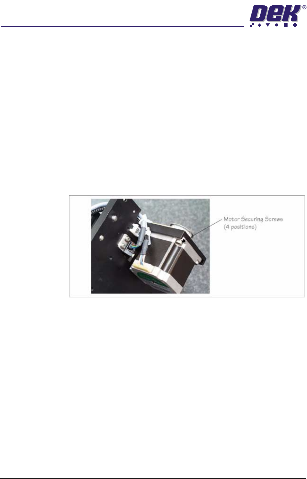
5. Placing the unit on a secure surface, slacken off the four screws securing
the stepper motor to the support plate, (figure below refers).
6. Remove the old drive belt. Fit new belt in position.
7. Using a cable tie wrap or similar, provide a loop around the top of the motor
body enabling the motor to be pulled using a force meter. Ensure that the
force meter is pulled in the direction which the drive belt is fitted, (Figure