265ProFlow.pdf - 第59页
TECHNI CAL REFEREN CE REPLACEM ENT PROC EDURES Chapter Issue 8 Dec 02 ProFlow Manual 1.55 below ref ers). 8. Pull the force meter unt il a tensio n of 3 to 4kgs is monitore d on the meter . T ighten the f our screws whil…
TECHNICAL REFERENCE
REPLACEMENT PROCEDURES
1.54 ProFlow Manual Chapter Issue 8 Dec 02
NOTE
Information on the ProFlow parameters are detailed under Menu Parame-
ters in the Machine Programming chapter of the User manual.
Information on the machine set up procedures are detailed in the Machine
Programming chapter of the User manual.
Drive Belt
Replacement
(fixed head
machines)
To replace the ProFlow drive belt the printhead mechanism must first be
removed from the print carriage, carry out the following procedure:
1. In Print Carriage Diagnostics, select Drive Carriage to Front Position.
Power down the machine, raise the machine covers.
2. Remove the ProFlow unit if fitted.
3. Disconnect all plugs from the printhead mechanism to the connector panel
on the print carriage.
4. Remove the printhead mechanism by unscrewing the four captive screws
securing the unit to the print carriage.
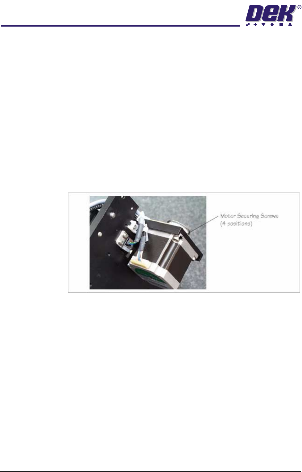
5. Placing the unit on a secure surface, slacken off the four screws securing
the stepper motor to the support plate, (figure below refers).
6. Remove the old drive belt. Fit new belt in position.
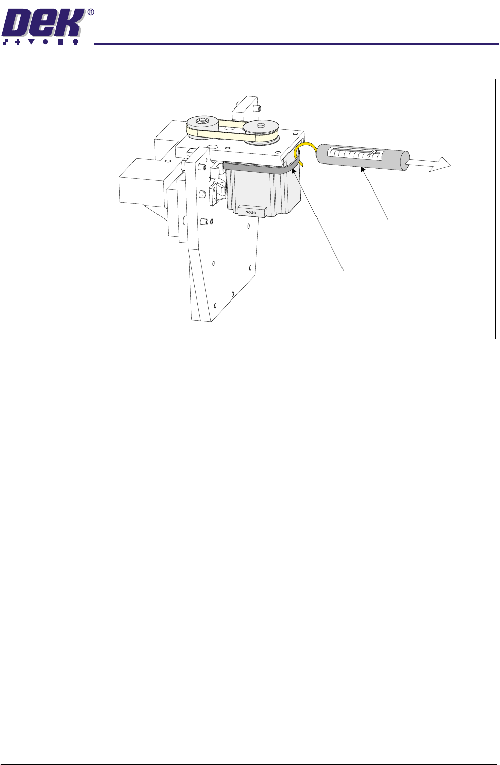
7. Using a cable tie wrap or similar, provide a loop around the top of the motor
body enabling the motor to be pulled using a force meter. Ensure that the
force meter is pulled in the direction which the drive belt is fitted, (Figure
TECHNICAL REFERENCE
REPLACEMENT PROCEDURES
Chapter Issue 8 Dec 02 ProFlow Manual 1.55
below refers).
8. Pull the force meter until a tension of 3 to 4kgs is monitored on the meter.
Tighten the four screws whilst the motor is under tension.
9. On completion re-fit the printhead mechanism to the print carriage and
re-connect all leads to the print carriage connector plate.
10. Re-fit ProFlow unit to printhead mechanism.
Force Meter
Tie-wrap
3kgs - 4kgs
Tension
TECHNICAL REFERENCE
CALIBRATIONS
1.56 ProFlow Manual Chapter Issue 8 Dec 02
CALIBRATIONS
ProFlow Contact
Position Setup
To set up the ProFlow contact height position carry out the following procedures:
1. Ensure the machine has initialized, if not switch power OFF and ON and
allow the machine to initialize.
2. Load a stencil with an off centre image.
3. Fit an empty transfer head to the ProFlow pressure mechanism. Remove
the cover.
NOTE
Ensure wipers and skis are fitted to the transfer head.
CAUTION
MACHINE JAMMING.
In order to prevent the inadvertent jamming of squee-
gee mechanical mechanisms, the following procedure must be carried out
in the correct sequence.
4. Position a 0.1mm shim on the stencil under the transfer head.
5. Select Maint. (F8).
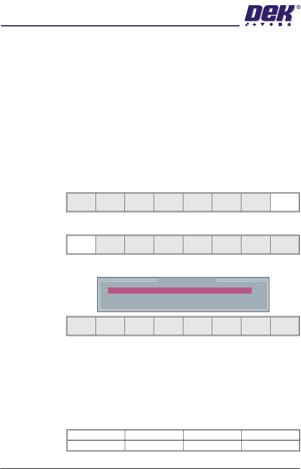
6. Select Calibrat ProFlow (F1).
The following window and menu bar is displayed:
NOTE
The ProFlow Downstop Position is only available on GSX, Lt and Infinity
machines only.
7. For fixed head machines go to Step 11, for GSX, Lt and Infinity machines
continue with Step 8.
8. Using the Next key (F4), highlight PFLOW DSTOP POS.
This parameter pre-tensions the squeegee suspension springs to provide
ProFlow with a zero pressure datum.
Run Head
Knead
Paste
Clean
Screen
Adjust Setup Monitor Maint.
Calibrat
ProFlow
Calibrat
Offset
Calibrat
Vision
House
Keeping
Set
Prefs
Diagnost
Test
Cycles
Exit
ProFlow Calibrations
PFLOW CONTACT POS.
PFLOW DSTOP POS.
0.0
0.0
mm
mm
Move to
Position
Restore
Defaults
Next Previous Incr. Decr. Exit
Minimum Maximum Increment Default
- 10mm +10mm 0.1mm 0.0mm