265ProFlow.pdf - 第61页
TECHNI CAL REFEREN CE CALI BRA TION S Chapter Issue 8 Dec 02 ProFlow Manual 1.57 9. Using the Incr . and De cr . keys (F6 - F7) , set the Downstop Position to 4.0 mm . 10. Select Move to Positi on (F1), the downstop is d…
TECHNICAL REFERENCE
CALIBRATIONS
1.56 ProFlow Manual Chapter Issue 8 Dec 02
CALIBRATIONS
ProFlow Contact
Position Setup
To set up the ProFlow contact height position carry out the following procedures:
1. Ensure the machine has initialized, if not switch power OFF and ON and
allow the machine to initialize.
2. Load a stencil with an off centre image.
3. Fit an empty transfer head to the ProFlow pressure mechanism. Remove
the cover.
NOTE
Ensure wipers and skis are fitted to the transfer head.
CAUTION
MACHINE JAMMING.
In order to prevent the inadvertent jamming of squee-
gee mechanical mechanisms, the following procedure must be carried out
in the correct sequence.
4. Position a 0.1mm shim on the stencil under the transfer head.
5. Select Maint. (F8).
6. Select Calibrat ProFlow (F1).
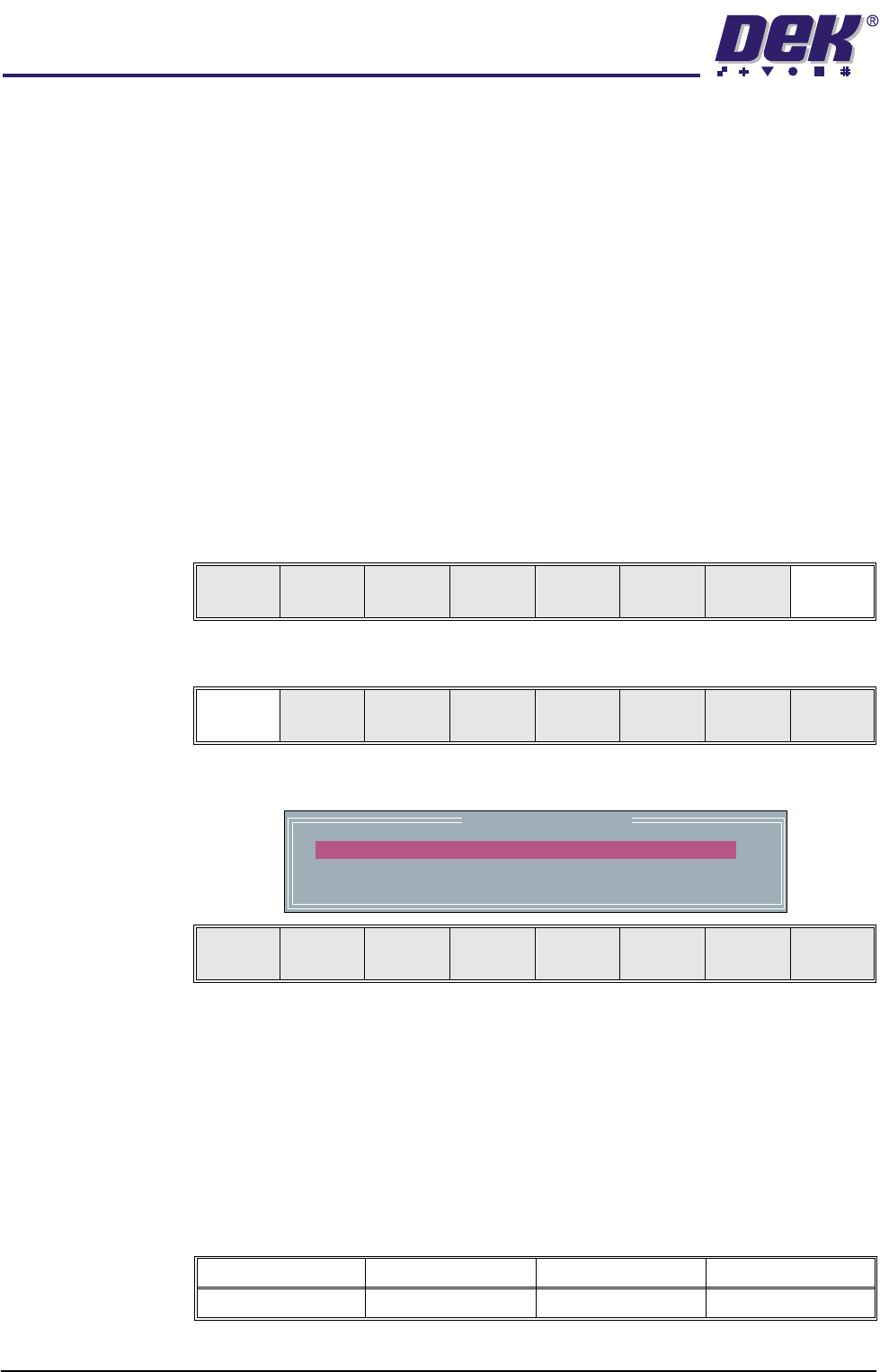
The following window and menu bar is displayed:
NOTE
The ProFlow Downstop Position is only available on GSX, Lt and Infinity
machines only.
7. For fixed head machines go to Step 11, for GSX, Lt and Infinity machines
continue with Step 8.
8. Using the Next key (F4), highlight PFLOW DSTOP POS.
This parameter pre-tensions the squeegee suspension springs to provide
ProFlow with a zero pressure datum.
Run Head
Knead
Paste
Clean
Screen
Adjust Setup Monitor Maint.
Calibrat
ProFlow
Calibrat
Offset
Calibrat
Vision
House
Keeping
Set
Prefs
Diagnost
Test
Cycles
Exit
ProFlow Calibrations
PFLOW CONTACT POS.
PFLOW DSTOP POS.
0.0
0.0
mm
mm
Move to
Position
Restore
Defaults
Next Previous Incr. Decr. Exit
Minimum Maximum Increment Default
- 10mm +10mm 0.1mm 0.0mm
TECHNICAL REFERENCE
CALIBRATIONS
Chapter Issue 8 Dec 02 ProFlow Manual 1.57
9. Using the Incr. and Decr. keys (F6 - F7), set the Downstop Position to
4.0mm.
10. Select Move to Position (F1), the downstop is driven to the position set.
11. Using the Next key (F4) highlight PFLOW CONTACT POS.
This parameter sets the height of the ProFlow printhead so that it just
touches the stencil surface.
12. Using the Incr. or Decr. keys (F6 - F7), set the Contact Position to 5.5mm
for fixed head machines and 4.0mm for GSX, Lt and Infinity machines.
13. Select Move to Position (F1), the ProFlow unit is driven to the position set.
NOTE
Correct contact height is when the shim is just held between the transfer
head wipers and stencil. At this position it is not possible to slide the shim
sideways past the transfer head skis. If correct contact height is not yet
achieved, carry out the following steps:
14. If correct contact height is achieved go to Step 18. If correct contact height
is not yet achieved, continue with Step 15.
15. Using the Incr. or Decr. keys (F6 - F7), increase or decrease the Contact
Position set height by 0.5mm (eg 5.0mm or 6.0mm for fixed head machines,
3.5mm or 4.5mm for GSX, Lt and Infinity machines).
NOTE
Normally the contact position is between the range of 4mm - 8mm (nomi-
nally 6mm) for fixed head machines and 2mm - 6mm (nominally 4.0mm)
for Infinity, GSX and Lt machines.
16. Select Move to Position (F1), the ProFlow unit is driven to the position set.
17. Repeat Steps 15 and 16, varying the set position, until the correct contact
height is achieved.
18. Select Exit (F8).
19. Select Exit (F8)
20. Open the front printhead cover and remove the shim. Remove empty
transfer head, if necessary.
21. Close the front printhead cover.
22. Press the System button.
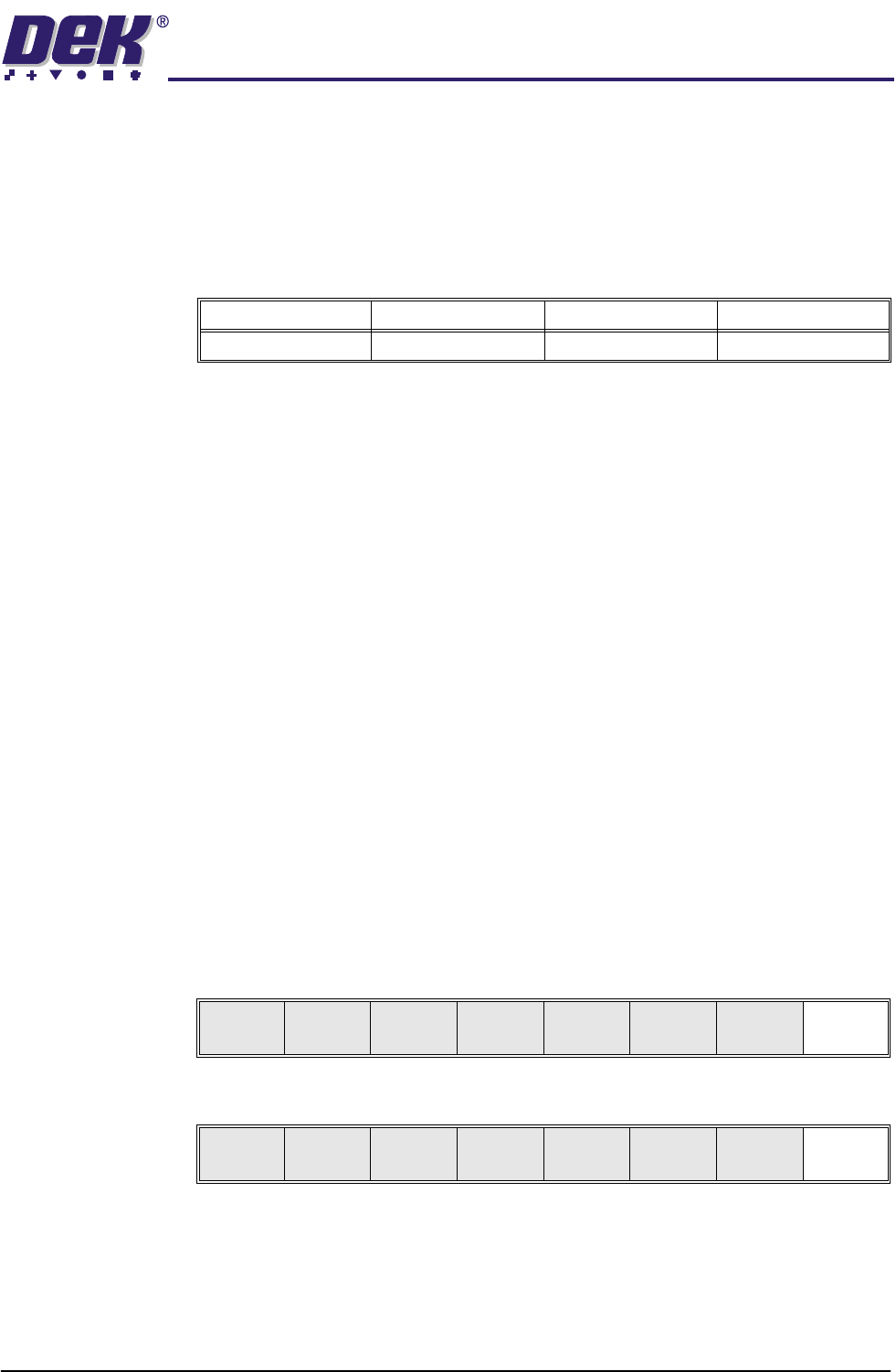
Minimum Maximum Increment Default
- 10mm +10mm 0.1mm 0.0mm
Move to
Position
Restore
Defaults
Next Previous Incr. Decr. Exit
Calibrat
ProFlow
Calibrat
Offset
Calibrat
Vision
House
Keeping
Set
Prefs
Diagnost
Test
Cycles
Exit
TECHNICAL REFERENCE
FAULT FINDING
1.58 ProFlow Manual Chapter Issue 8 Dec 02
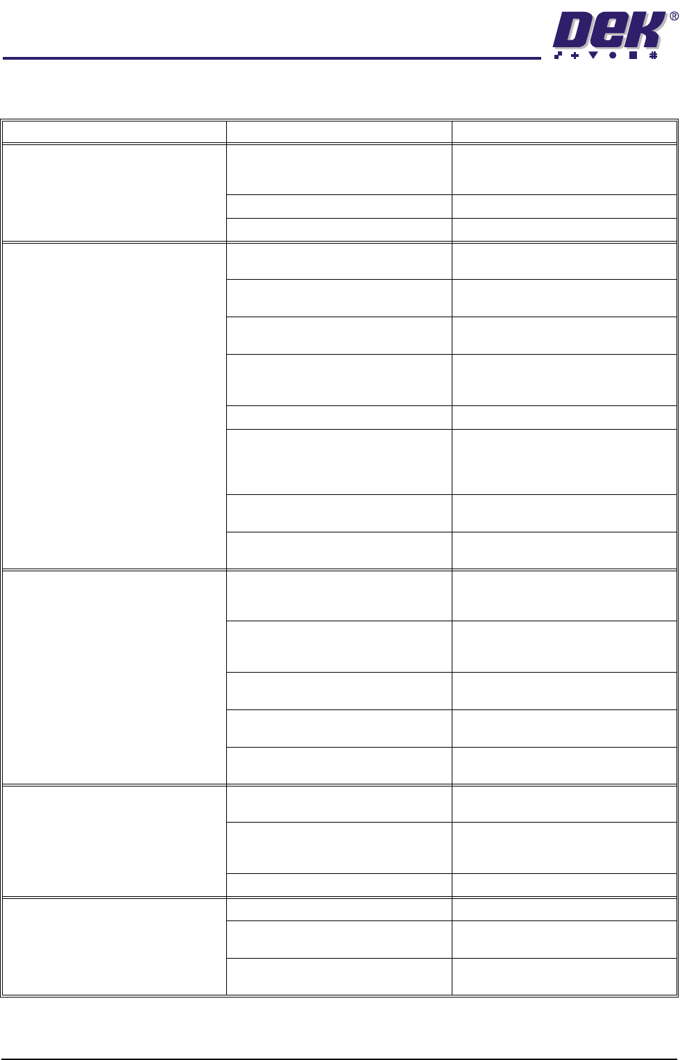
FAULT FINDING
Symptom Possible Causes Possible Solutions
Leakage between the skis and wipers Pneumatic paste pressure set too high. reduce paste pressure or increase
speed. Check settings, mechanical
security.
Incorrect contact position. Try alternative set up method.
Old issue wipers or skis fitted. Ensure that the latest hardware is fitted.
Stencil or wiper damage Foreign matter between the board and
stencil.
Ensure boards are clean and flat when
entering the machine.
First side components not seating in the
tool nest correctly.
Check tooling nest/ first side place-
ment.
Metal edge wipers not being used. Ensure the latest ProFlow hardware is
fitted.
Stencil design not suitable for use with
ProFlow.
Large apertures need support bars, top
side of laser cut stencils must be
smooth.
Imaging speed too high. Reduce print carriage speed.
Bowed boards entering the machine
not being flattened by clamping pres-
sure.
Ensure the quality of raw materials con-
forms to specification. Bowing less
than 1% of diagonal dimension of
board.
Unsupported stencil. Support the stencil to keep the top sur-
face of the as flat as possible.
Cassette empty. Replace cassette and check adjust-
ment of paste low sensor.
Bridging Variation in stencil height due to
foreign matter between board and
stencil.
Ensure the boards are clean and flat,
the underside of the stencil is clean and
free from damage.
Bad board support causing the board to
bow upwards.
Modify the board support tooling
strategy and check that the rail to table
height is set correctly.
Pneumatic pressure too high. Reduce paste pressure or increase
print carriage speed.
Print carriage speed too low. Increase print carriage speed or reduce
pneumatic pressure
Solder paste slump. Control the temperature in the pre-
placement.
Bridging at the end of the print stroke Rail to table height incorrectly set. Check and reset rail to table height
dimension.
Pads too close to the edge of the board. Board design for DEK machines
requires a 5mm distance from the
board edge to the apertures.
Board clamps not level or parallel. ECB 638
Print wedging Excess system pressure. Reduce system pressure.
Uncontrolled system pressure. Use the alternative downstop and con-
tact setting to set the downstop solid.
Print speed too fast for the paste being
used.
Change the print speed.