265ProFlow.pdf - 第8页
TECHNIC AL RE FERENCE MODULE OVER VIEW 1.4 ProFlow Manual Chapter Issue 8 Dec 02 Figure 1-3 ProFlow Fitted to Mac hine (GSX, Lt and Infinity) View on ArrowA Front View of Print Carriage Showing ProFlow Fitted (cassette o…
TECHNICAL REFERENCE
MODULE OVERVIEW
Chapter Issue 8 Dec 02 ProFlow Manual 1.3
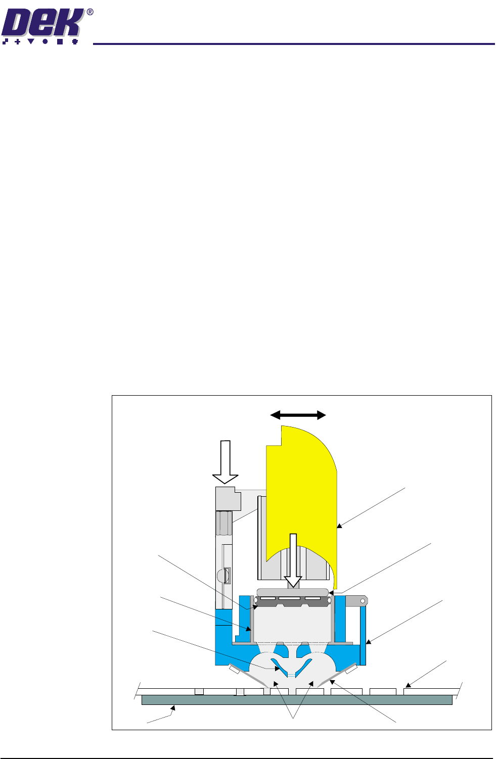
Operation ProFlow operates in the Y and Z axes (horizontal and vertical planes).
The unit is raised and lowered to the screen by means of the rear squeegee
stepper motor, or for fixed head machines, the special ProFlow printhead
mechanism.
A downward force is applied to the ProFlow transfer head directly onto the
stencil which provides:
• A Positive seal between the transfer head and stencil eliminating leakage
above the stencil.
• Improved gasketing effect to give the best possible seal between stencil
and board.
The horizontal movement, driven by the machine print carriage motor, moves
the unit across the stencil in a forward and reverse direction (Y axis). A print
cycle may consist of a single movement in the Y axis, (forward or backwards).
Paste pressure (pneumatic pressure), is applied to the piston crosshead exert-
ing a force onto the print material which, in turn, forces print material into the
ProFlow conditioning chamber and into the stencil apertures.
As the unit moves across the stencil, the trailing wiper within the transfer head,
lifts the print material from the screen surface creating a rolling movement of
material within the conditioning chamber. The volume of material, under
pressure from the piston crosshead, is kept at a constant level within the
chamber.
Figure 1-2 ProFlow Cross Section (with Cassette Option)
ProFlow Pressure
Mechanism
Transfer
Head
Stencil
Board
ProFlow Movement (Y Axis)
Wiper
Piston
Crosshead
Pneumatic
Pressure
System Pressure
Print Material
Side Chambers
Cassette
Nozzle
Cassette
Plunger
TECHNICAL REFERENCE
MODULE OVERVIEW
1.4 ProFlow Manual Chapter Issue 8 Dec 02
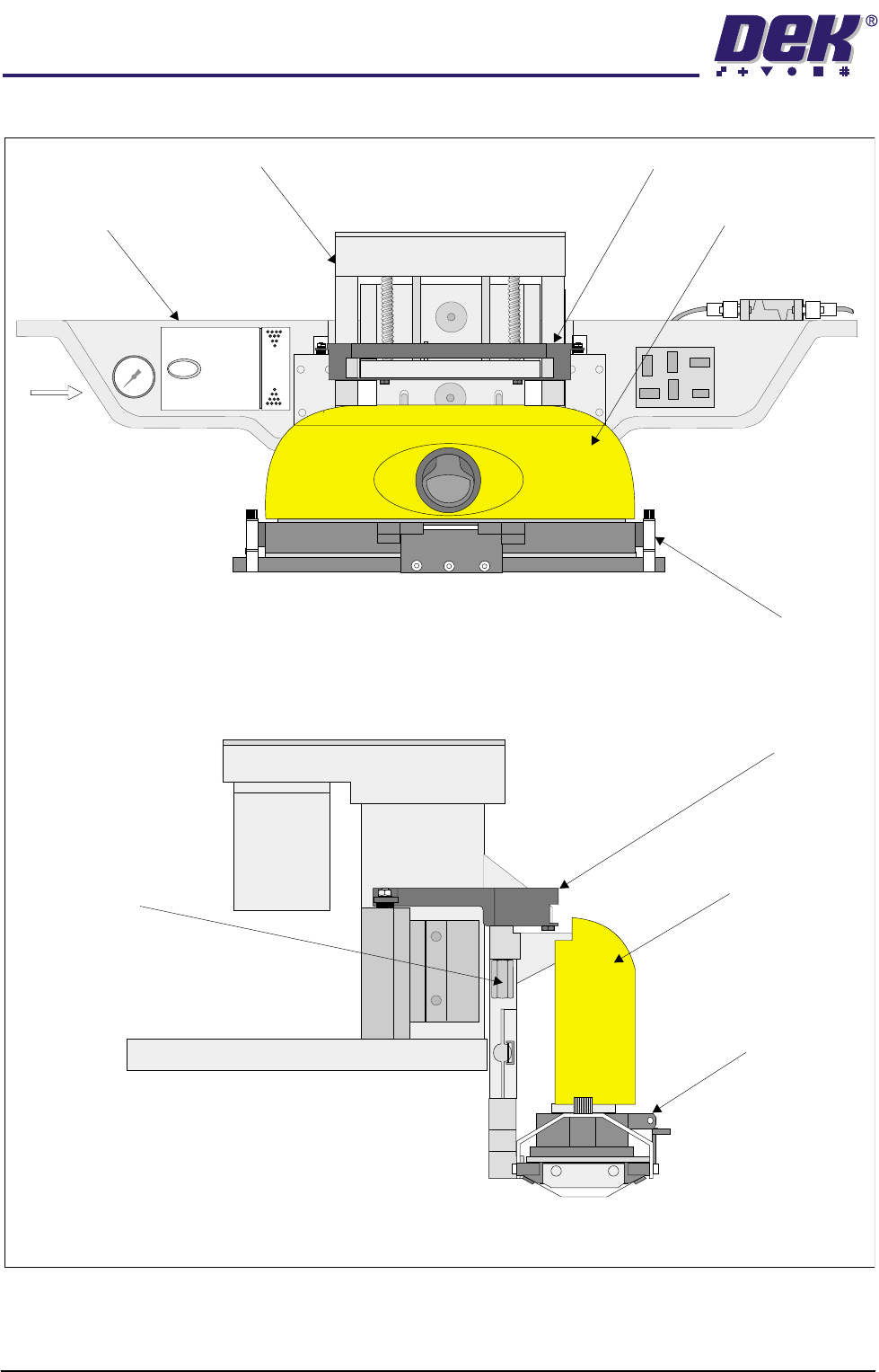
Figure 1-3 ProFlow Fitted to Machine (GSX, Lt and Infinity)
View on ArrowA
Front View of Print Carriage Showing ProFlow Fitted (cassette option)
Downstop
Rear Squeegee
Mount
Attachment Points
(2 positions)
ProFlow Pressure
Mechanism
ProFlow
Transfer Head
Printhead Drive Mechanism
Downstop
Machine Print Carriage
ProFlow Pressure
Mechanism
ProFlow Transfer Head
A
TECHNICAL REFERENCE
MODULE OVERVIEW
Chapter Issue 8 Dec 02 ProFlow Manual 1.5
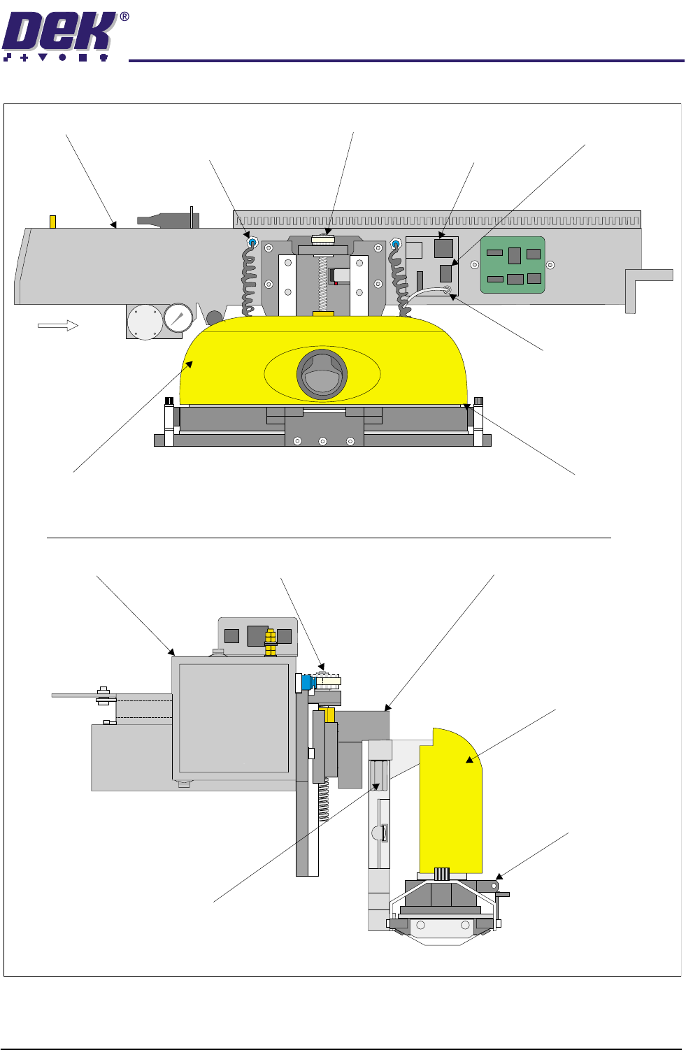
Figure 1-4 ProFlow Fitted to Machine (fixed head machines)
View on Arrow A (air line omitted for clarity)
Front View of Print Carriage Showing ProFlow Fitted (cassette option)
ProFlow Mechanism
Drive
Machine Print
Carriage
ProFlow Pressure Mechanism ProFlow Transfer Head
A
ProFlow Fitted/Paste
Low Connector
ProFlow Pneumatic
Connectors (2 Positions)
ProFlow Printhead Mechanism
Bearing Block
Motor Drive PulleyPrint Carriage
ProFlow Motor
Connector
ProFlow Home
Sensor Connector
ProFlow Mechanism - Attachment
Points (in 2 positions)
ProFlow Pressure
Mechanism
ProFlow
Transfer Head