00191332-01.pdf - 第140页
3 Calibration Functions User Manual Test Program SITEST 3.11 Calibration of the Coplanarity Laser M odule (SIPLACE 80F4/80F5) Software Version 405.xx Issue 01/99 3 - 28 ● Clic k on the Calibrate module button. The focus …
User Manual Test Program SITEST 3 Calibration Functions
Software Version 405.xx Issue 01/99 3.11 Calibration of the Coplanarity Laser Module (SIPLACE 80F4/80F5)
3 - 27
3.11 Calibration of the Coplanarity Laser Module
(SIPLACE 80F
4
/80F
5
)
NOTE
Prior to the calibration of the coplanarity module, all calibration operations described earlier in this chapter must
have been performed (except for the calibration of the flip-chip camera and the IC- and RV nozzle changer).
3
● Carry out the preparatory steps proceeding as described in section 3.1. However, place the coplanarity
calibration tool into the "calibration tool pocket" in lieu of the "normal" calibration tool (see Fig. 3.12.1).
● In the "IC head" display (see Fig. 0.3.6) click on the icon to switch to the "Coplanarity
functions" display.
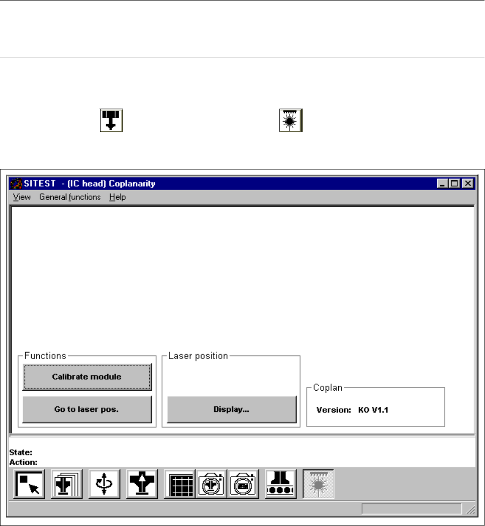
Fig. 3.11.1 "Coplanarity functions" Display
Overview of the functions:
– Calibrate module to calibrate the coplanarity module
– Go to laser pos. to approach the laser with the PCB camera to check the laser position
– Display... to display the laser position and focus height determined

3 Calibration Functions User Manual Test Program SITEST
3.11 Calibration of the Coplanarity Laser Module (SIPLACE 80F4/80F5) Software Version 405.xx Issue 01/99
3 - 28
● Click on the
Calibrate module
button.
The focus height is now measured and the x and y-positions of the laser determined.
● If you wish to view the values determined for the laser position and focus height, click on the
Display...
button.
NOTE
The laser module’s version number is displayed in the "Coplan" field.
● Click on the icon to return to the main view.

User Manual Test Program SITEST 3 Calibration Functions
Software Version 405.xx Issue 01/99 3.12 Measuring the Position of PCB Reference Corner I (and that of PCB Reference Corner II)
3 - 29
3.12 Measuring the Position of PCB Reference Corner I
(and that of PCB Reference Corner II)
NOTE
Verify that the calibration data for the PCB camera, segment offset II (RV-PCB camera offset) and machine
zero point have already been determined.
3
● Load a PCB with a light-colored surface into the center conveyor using the conveyor functions (see
chapt. 2, section 2.5).
NOTE
Measuring the PCB reference corner positions on the SIPLACE 80S-20/S-23 machine type can only be per-
formed by means of gantry 1.
If a dual conveyor is installed on the machine, a PCB must be loaded on the right conveyor track ("PCB
conveyor 1") and
on the left conveyor track ("PCB conveyor 2") in order to be able to determine the position
of PCB reference corners
and . To this end, select the desired conveyor in each case before the respective
PCB is loaded (see chapt. 2, section 2.5).
The location of the PCB reference corners
and differs depending on the conveyor type used.
The following graphical display gives a schematic view of the positions of the PCB reference corners.
3