00191332-01.pdf - 第161页
User Manual Test Program SITEST 4 Mapping Software Version 405.xx Issue 01/99 4.4 IC Mapping 4 - 13 4.4 IC Mapping NOTE Prior to the perfo rmance of IC mappin g make sur e that PCB mapping ha s alrea dy been c arried ou …

4 Mapping User Manual Test Program SITEST
4.3 RV Mapping Software Version 405.xx Issue 01/99
4 - 12
● If a dual conveyor is installed, activate the radio button for the conveyor track for which mapping is to be
performed.
● Click on the
Start
button in the "RV mapping of selected gantry" field and follow the directions displayed
on the screen.
Gantry 2 now performs the mapping run.
After the mapping run has been completed without any errors, the data thus determined is automatically
saved.
● If a dual conveyor is installed, activate the radio button for the conveyor track for which mapping has not
yet been performed.
● Click again on the
Start
button in the "RV mapping of selected gantry" field and follow the directions
displayed on the screen.
Gantry 2 performs the mapping run on the selected conveyor track.
After the mapping run has been completed without any errors, the data thus determined is automatically
saved.
● Click on the icon to return to the main view.
NOTE
RV mapping can also be performed using the
Calibrate machine...
-->
Head mapping
function (see chapt. 3,
section 3.2). On SIPLACE 80S-20/S-23 machine types, this function is used to perform automatically the map-
ping procedure, first for gantry 1 and then for gantry 2.
If a dual conveyor is installed on the machine, mapping is performed first on the right and then on the left
conveyor track.
4
CAUTION
As the data will be overwritten during PCB mapping, it is necessary that RV mapping and IC mapping
(SIPLACE 80F
4
/F
5
) be repeated after every PCB mapping operation.
4
User Manual Test Program SITEST 4 Mapping
Software Version 405.xx Issue 01/99 4.4 IC Mapping
4 - 13
4.4 IC Mapping
NOTE
Prior to the performance of IC mapping make sure that PCB mapping has already been carried out.
4
● Carry out the preparatory steps as described in section 4.1.
Additional prerequisites are:
– Segment offset II (RV-PCB camera offset) must already have been determined.
– The calibration tool must be in the calibration tool pocket.
– The calibration tool position must already have been determined.
– The IC camera must have been completely calibrated.
– On the IC head, a type 416 nozzle must be attached.
● In the main view SIPLACE 80F
4
/80F
5
click on the icon to switch to the "IC head" display.
● Click on the icon to switch to the "IC mapping" display.
4 Mapping User Manual Test Program SITEST
4.4 IC Mapping Software Version 405.xx Issue 01/99
4 - 14
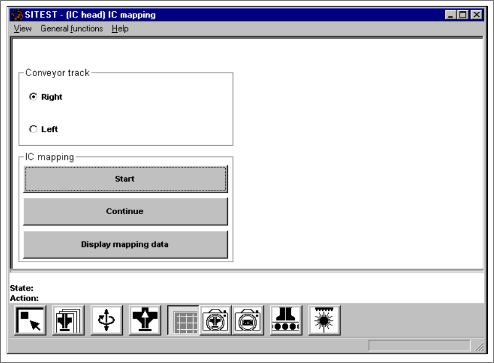
Fig. 4.4.1 "IC mapping" Display
The following functions are available in the "IC mapping" display:
– Right to select the right conveyor track
– Left to select the left conveyor track of a dual conveyor
– Start to start the mapping run
– Continue to continue mapping
– Display mapping data to display the mapping data determined
● If a dual conveyor is installed, activate the radio button for the conveyor track for which mapping is to be
performed.
● Click on the Start button and follow the directions displayed on the screen.
The gantry performs the mapping run. After the mapping run has been completed without any errors, the
data thus determined is automatically saved.
● If a dual conveyor is installed, activate the radio button for the conveyor track for which mapping has not
yet been performed.
● Click again on the Start button and follow the directions displayed on the screen.
The gantry performs the mapping run on the selected conveyor track. After the mapping run has been
completed without any errors, the data thus determined is automatically saved.