00191332-01.pdf - 第92页
2 Functions for the Adjustment of the Machine User Manual Test Program SITEST 2.2 Head Board Software Version 405.xx Issue 01/99 2 - 20 ● T o mea sure the curre nt vacuum values in the h oldin g circuit , click on th e V…
User Manual Test Program SITEST 2 Functions for the Adjustment of the Machine
Software Version 405.xx Issue 01/99 2.2 Head Board
2 - 19
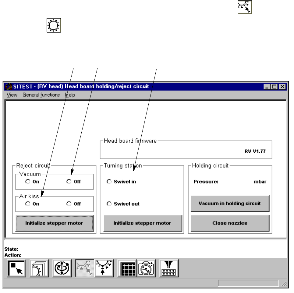
2.2.2 Functions of the RV Head in the Holding/Reject Circuits
● If you wish to test the head functions in the holding and reject circuits, click on the icon in the
"RV head" display (see Fig. 0.3.5) to switch to the "Head board RV head, holding and reject cir-
cuit".
Fig. 2.2.2 "Head board RV head, holding/reject circuit" Display
Legend pertaining to Fig. 2.2.2
➀ to switch the vacuum on/off
➁ to switch the air-kiss function at the reject station on/off
➂ to swivel the dp-drive in/out
● If you wish to test, for example, the head functions during the swivel-in motion of the dp-drive, activate
the corresponding radio button in the "Turning station" field (see Fig. 2.2.2).
● To move the stepper motor for the swivel-in mechanism of the dp-station into neutral position, click on
the Initialize stepper motor button in the "Turning station" field.
➀➁
➂

2 Functions for the Adjustment of the Machine User Manual Test Program SITEST
2.2 Head Board Software Version 405.xx Issue 01/99
2 - 20
● To measure the current vacuum values in the holding circuit, click on the
Vacuum in holding circuit
button. The measured value is displayed above the button.
NOTE
Prior to the execution of the "Close nozzles" function, a head reference run must have been performed on
the RV head (see section 1.4.3).
2
● If you wish to measure the vacuum with the nozzles closed, click on the
Close nozzles
button prior to
the start of the vacuum measurement.
User Manual Test Program SITEST 2 Functions for the Adjustment of the Machine
Software Version 405.xx Issue 01/99 2.2 Head Board
2 - 21
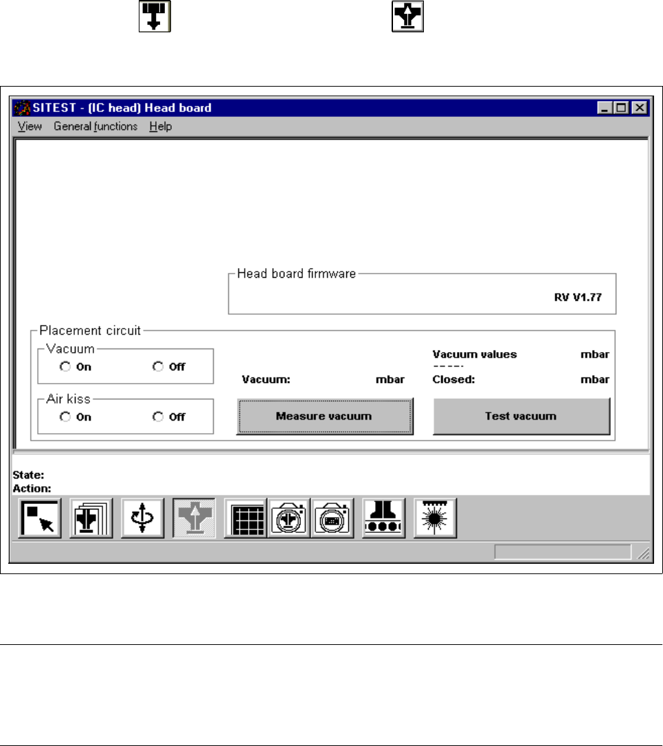
2.2.3 Functions of the IC Head in the Placement Circuit
(SIPLACE 80F
4
/80F
5
)
● In the "IC head" display (see Fig. 0.3.6), click on the icon to switch to the "Head board IC
head" display.
Fig. 2.2.3 "Head board IC head" Display
NOTE
Since the buttons and radio buttons in the "Head board IC head" have the same functions as the identically
labeled buttons and radio buttons in the "Head board RV head, placement and pick-up circuit" display (see sec-
tion 2.2.1, Fig. 2.2.1), they will not be described again in this section. 2