00198501-02_IM_711.1_R18-1_EN.pdf - 第64页
Station Software V ersion 711.1 (R 18 - 1) / Installat ion Manual 05/2018 Edition 64 7.8 Necessary Calib ration Steps After the first boot ing of the stat ion software, some c alibration step s are required. Requirements…
Station Software Version 711.1 (R18-1) / Installation Manual 05/2018 Edition
63
7.5 TX-Series (V1 and V2) Placement Machines
► When the TX placement machines are booted for the first time you have to select the following
options manually:
– If SIPLACE JTF-ML is used, select the X-Table, multi tray feeder support option for the
JTF-ML Table 40X on Location 1.
– If no reject plate has been installed, you have to disable this option explicitly.
7.6 Checking/Updating the Embedded Software
If the correct embedded SW versions are not available on the machine, the machine boot gets
interrupted.
► In this case, perform an embedded SW download.
► Start an overall reference run for the machine.
7.7 Storage Location of the Machine Files (Calibration Data etc.)
The machine-specific configuration, measurement and parameter data is stored in XML files under
C:\Sirio\Work\Individual. These XML files contain all calibration data.
Station Software Version 711.1 (R18-1) / Installation Manual 05/2018 Edition
64
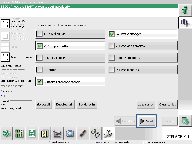
7.8 Necessary Calibration Steps
After the first booting of the station software, some calibration steps are required.
Requirements:
– The embedded SW versions have been updated.
– The reference run has been successfully performed.
– A calibration nozzle (1235) has to be available on every C&P20A placement head at
segment 1.
Figure 7-2: Required calibration steps
► Select the calibration steps that are highlighted in the figure and click on Next.
► Select all possible components in the following input masks (all conveyor lanes, all gantries, all
nozzle changers).
Station Software Version 711.1 (R18-1) / Installation Manual 05/2018 Edition
65
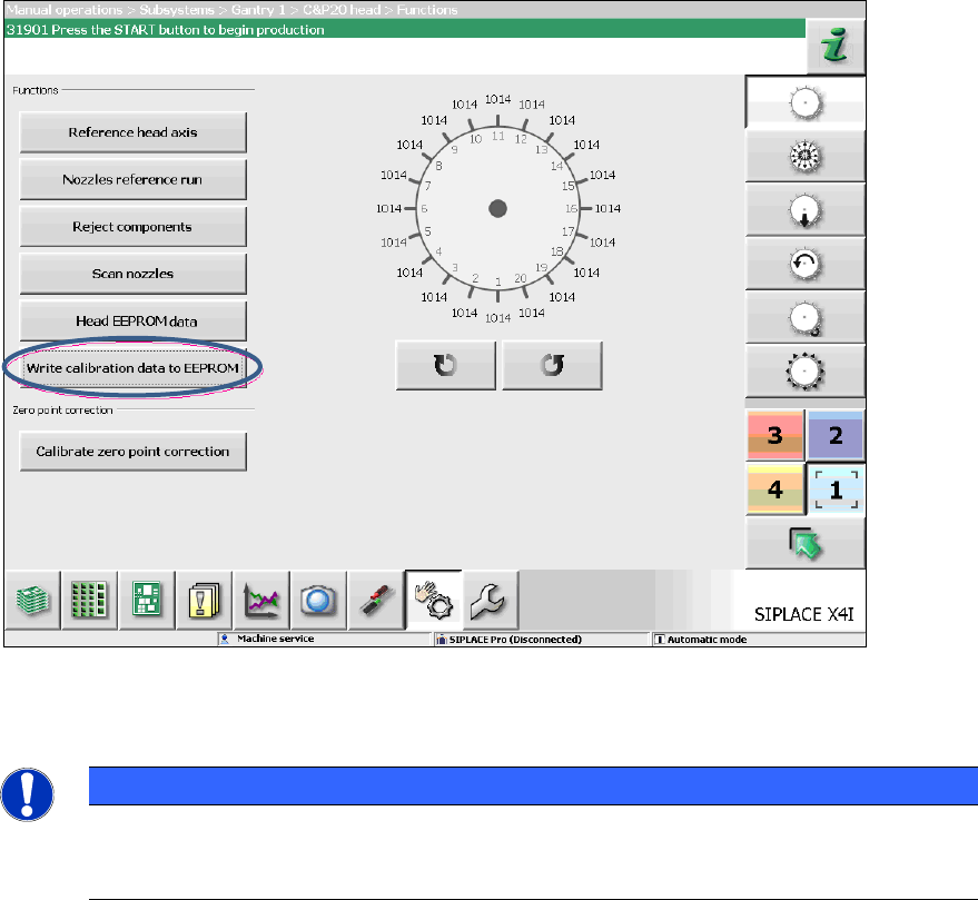
7.9 Storing Calibration Data in the EEPROM
In order to use the fast head exchange feature, the head specific calibration data has to be stored
in the EEPROM. For placement heads with no head specific calibration data stored within the
EEPROM, the available data on the station computer will be stored in the EEPROM of the
respective placement head as follows.
Requirement:
The embedded SW versions have been updated.
Figure 7-3: Storing calibration data in the EEPROM
► Perform the highlighted function for each placement head.
NOTICE
After the storing calibration data step, the message 37200 Changed heads
detected should disappear. Otherwise you will have to reboot the machine. If the
message still is displayed after rebooting, please inform the ASM Service.