Service Manual HS60.pdf - 第300页
7 DL M2 Co llec t &P lace Head H S-6 0 S erv ic e Manu al 7. 13 R e plac in g t he Z-a x is dr iv e (0 0 34 10 11- 01) 03/2 00 3 US I ss ue 298 . F ig. 7. 13 - 1 Di sma nt lin g the Z -ax is d riv e Key t o Fi g. 7.1…

HS-60 Service Manual 7 DLM2 Collect&Place Head
03/2003 US Issue 7.13 Replacing the Z-axis drive (00341011-01)
297
7.13 Replacing the Z-axis drive (00341011-01)
7.13.1 Tools and equipment
– Set of DIN 911 Allen keys
– TSM belt tension measuring device, item no. 00326015-01
– "Measuring belt tensions" instructions
7.13.2 Parts
Z-axis drive, item no. 00341011-01 7
7.13.3 Dismantling the Z-axis drive
Æ Switch the placement system off and secure it to prevent switching on again as described in
Section 7.4
, page 261.
Æ Remove the plugs from sockets X3 and X4 on the intermediate distribution board
(see Fig. 7.5 - 1
.
Æ Undo the four M3x5 hexagon socket-head screws with locking varnish (item 1 in Fig.
7.13 - 1
).
Æ First undo the upper M2.5x12 hexagon socket-head screw (item 3 in Fig. 7.13 - 1) of the motor
clamp fitting 2 (item 4 in Fig. 7.13 - 1
), then the lower one.
Æ Undo the two M3x14 hexagon socket-head screws (item 6 in Fig. 7.13 - 1 of the motor clamp
(item 5 in Fig. 7.13 - 1
).
7
7 DLM2 Collect&Place Head HS-60 Service Manual
7.13 Replacing the Z-axis drive (00341011-01) 03/2003 US Issue
298
.
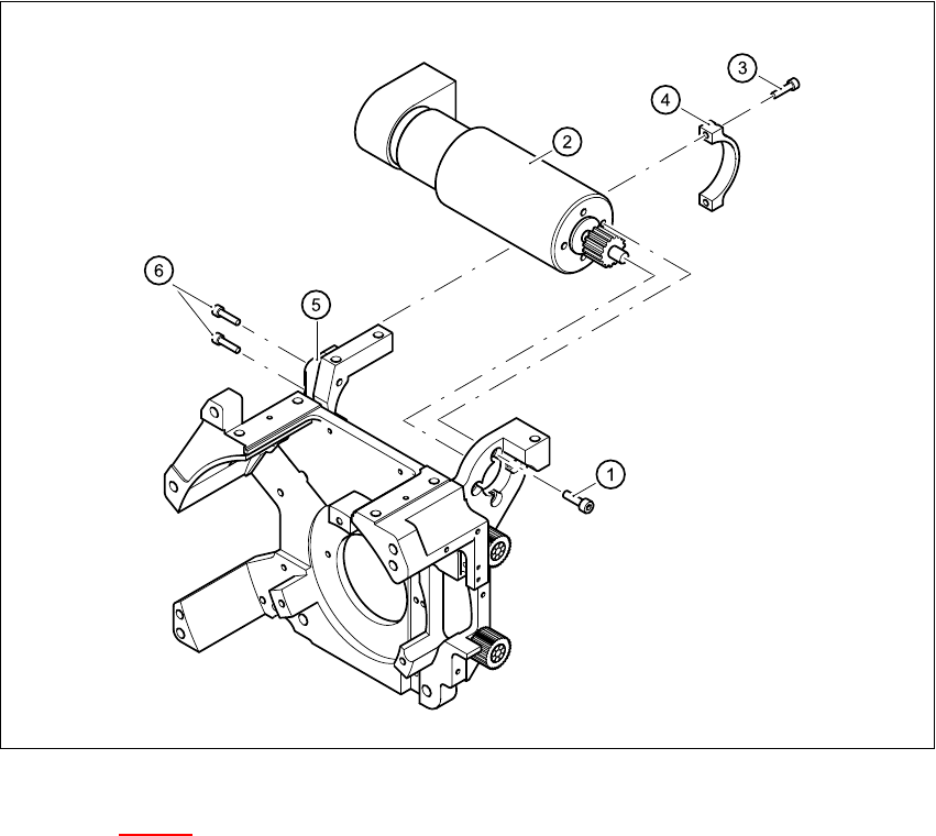
Fig. 7.13 - 1 Dismantling the Z-axis drive
Key to Fig. 7.13 - 1
(1) 4 x M3x5 hexagon socket-head screw with locking varnish
(2) Z-axis drive
(3) 2 x M2.5x12 hexagon socket-head screw
(4) Motor clamp fitting 2 / DLM2
(5) Motor clamp fitting / DLM2
(6) 2x M3x14 hexagon socket-head screw
7
Æ Carefully remove the Z-axis drive together with the cables.

HS-60 Service Manual 7 DLM2 Collect&Place Head
03/2003 US Issue 7.13 Replacing the Z-axis drive (00341011-01)
299
7.13.4 Fitting the Z-axis drive
Æ Insert the Z-axis drive.
Æ Make sure that the teeth of the toothed belts engage in the teeth of the motor pinion.
Æ Use the four M3x5 hexagon socket-head screws to fix the Z-axis drive.
Æ Tension the Z toothed belt by pushing the Z drive unit upwards.
7.13.5 Settings
Æ Use the belt tension measuring device to check the tension of the toothed belt (see setting in-
structions).
Æ Tighten the two M3x14 hexagon socket-head screws (item 6 in Fig. 7.13 - 1) for fixing the mo-
tor clamp (item 5 in Fig. 7.13 - 1
).
Æ Tighten the two M2.5x12 hexagon socket-head screws (item 3 in Fig. 7.13 - 1) for fixing the
motor clamp 2 (item 4 in Fig. 7.13 - 1
).
PLEASE NOTE:
Now tighten the hexagon socket head screws on the Z-drive unit and the motor clamp. 7
7
Frequency (Hz)
before continuous operation
Frequency (Hz)
after continuous operation
Toothed belt T2 / DLM2 280 ± 10 280 ± 10
Tab. 7.13 - 1 Belt tension values before and after continuous operation