Service Manual HS60.pdf - 第313页
HS -60 Se rvic e Ma nual 7 DLM2 Co l lect&Plac e Head 03/ 2 0 03 US Is sue 7.1 7 DLM 2 Repla cing the st ar dri ve (0 0368 077-0 1) 311 7.17 DLM2 Repla cing the s t ar drive (0 0368077-01 ) 7.17.1 T ools an d equipm …

7 DLM2 Collect&Place Head HS-60 Service Manual
7.16 Replacing the star (00341181-01) 03/2003 US Issue
310
Æ Remove the gauge pin from the gauge for the star.
Æ Carry out the star axis reference run.
Æ Check that the star zero point correction value that you entered is correct:
Æ Insert the gauge pin into the segment once more.
It must slide in easily.
Æ Remove the gauge pin once more.
Æ Detach the gauge for the star from the collect&place head.
RISK OF HEAD CRASH
Always remove the gauge for the star, otherwise parts of the machine may be damaged. 7
Æ Select "Save MA Data".
Æ Remove the gauge and all tools from the machine.
Æ Wear laboratory gloves when handling the sleeves.
Step the star and return all the sleeves to their correct positions.
Æ Calibrate the collect&place head or machine, as required.

HS-60 Service Manual 7 DLM2 Collect&Place Head
03/2003 US Issue 7.17 DLM2 Replacing the star drive (00368077-01)
311
7.17 DLM2 Replacing the star drive (00368077-01)
7.17.1 Tools and equipment
– Set of DIN 911 Allen keys
– Gauge for the star (collect&place head / DLM2), article number 00326164-01
– Power pack for the collect&place head / DLM2, article number 00353277-01
– Tray for transporting the collect&place head
– Laboratory gloves
7.17.2 Parts
Star drive, digital / DLM2, article number 00368077-01 7
7.17.3 Dismantling the star drive
Æ Dismantle the intermediate terminal block as described in Section 7.10.3, page 288.
Æ Dismantle the front part of the collect&place head as described in Section 7.6.2, page 269.
Æ Dismantle the star as described in Section 7.16.3, page 304.
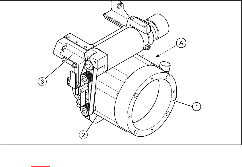
Æ Undo the four M5x16 hexagon socket head screws (item 2 in Fig. 7.17 - 1).
Æ Lift the star drive off the front part of the collect&place head.
7.17.4 Fit the star drive.
Æ
Place the star motor on the front part of the collect&place head so that the connecting cable
for the star drive points to the position marked (A) in Fig. 7.17 - 1
.
Æ Fix the star drive in place with the four M5x16 hexagon socket head screws (item 2 in Fig. 7.17
- 1).
Æ Fit and adjust the star as described in Sections 7.16.4 and 7.16.5.
Æ Fit the front part of the collect&place head as described in Section 7.6.3, page 272.
7 DLM2 Collect&Place Head HS-60 Service Manual
7.17 DLM2 Replacing the star drive (00368077-01) 03/2003 US Issue
312
7
Fig. 7.17 - 1 Replacing the star drive
Key to Fig. 7.17 - 1
(1) Star drive, digital / DLM2
(2) M5x16 hexagon socket head screws, 4x
(3) Front part of collect&place head
(A)Connecting cable for the star drive on this side 7