Service Manual HS60.pdf - 第100页
4 G ant ri es HS- 6 0 S erv ice Ma nu al 4. 2 S tru ct ure of th e ga ntry 03/ 200 3 US I ssue 98 The head mo unt supports t he collect&place head /DLM 2 and the head board (see item 4 in F ig. 4.2 - 4 ). 4 The PCB c…
HS-60 Service Manual 4 Gantries
03/2003 US Issue 4.2 Structure of the gantry
97
4
Fig. 4.2 - 5 Position of the gantry and compressed air distributors
Key
(1) Gantry distributor
(2) Compressed air distributor
4
The other three ribbon cables supply power and transmit control signals for the gantry axis drives.
They connect the gantry distributor (see item 1 in Fig. 4.2 - 5
) to the X/Y distributor (item 2 in Fig.
4.2 - 4
). 4
The gantry is supplied with compressed air via seven compressed air hoses. The lines are con-
nected to the compressed air distributor (see item 2 in Fig. 4.2 - 5
). They run in the trailing cable
and end at the inlet couplings (see item 7 in Fig. 4.2 - 4
) on the motor bracket (see item 9 in Fig.
4.2 - 4
). Seven compressed air lines continue from the outlet couplings (see item 8 in Fig. 4.2 - 4)
to the collect&place head. 4
The X-axis motor (see item 5 in Fig. 4.2 - 4
) moves the head mount (see item 4 in Fig. 4.2 - 4) in
the x direction with the aid of a toothed belt (see item 6 in Fig. 4.2 - 4
). The mount is fixed to three
shuttles (see item 1 in Fig. 4.2 - 6
) on the two recirculating ball screw units (see item 2 in Fig.
4.2 - 6
) on the underside of the gantry. This layout guarantees that movement of the X-axis is both
precise and generates very little friction. 4
1
2
4 Gantries HS-60 Service Manual
4.2 Structure of the gantry 03/2003 US Issue
98
The head mount supports the collect&place head /DLM2 and the head board (see item 4 in Fig.
4.2 - 4
). 4
The PCB centering and pick-up position detection components for the feeder modules are
mounted on the underside of the head mount. 4
4
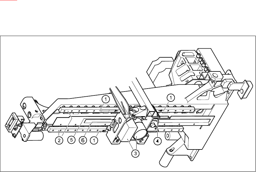
Fig. 4.2 - 6 Head mount - underside
Key
(1) Three shuttles on the two recirculating ball screw units
(2) Recirculating ball screw units
(3) Camera beneath the gantry for PCB centering and pick-up position detection for the feeder
modules
(4) Incremental encoder for the X-axis scale
(5) End position proximity switch 2
(6) End position proximity switch 1 and reference point for the X-axis
HS-60 Service Manual 4 Gantries
03/2003 US Issue 4.3 Parts overview
99
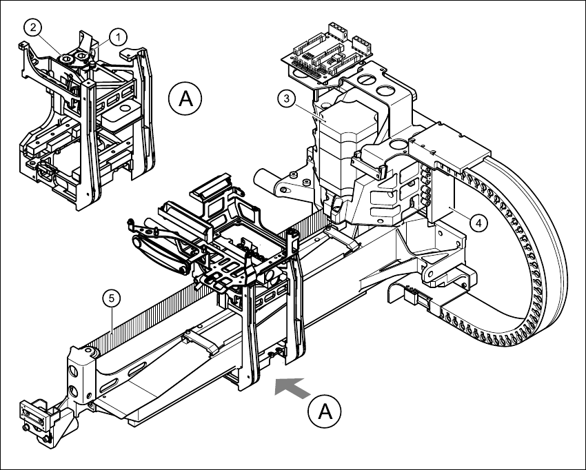
4.3 Parts overview
4
Fig. 4.3 - 1 Gantry - parts overview
Key
4
(1) Tensioning key (00329478-01) (2) Tensioning key (00329485-01)
(3) X-axis motor unit (00333167-03) (4) Linear motor, primary part (00333148-02)
(5) Toothed belt, Synchroflex 50ATS5/1205, E9/11 (00331076-02)